MD ARM INSTALLATION INSTRUCTIONS
MD ARM INSTALLATION - 12/3/19
Page 2 of 2
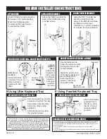
ADJUST ARM RESISTANCE
Using the 3/16” T-handle hex
wrench provided, turn the
screw in the MD arm clockwise
to lighten the arm’s load
resistance, or counter-clockwise
to increase the load resistance.
MONITOR TILT, ROTATION & ADJUST MONITOR DEPTH
MONITOR TILT
& ROTATE
Gently hold sides
of monitor. Tilt and
rotate to desired
position with ball
VESA.
ADJUST
MONITOR
DEPTH
Loosen the
adjustment
knob, move
the Paralink
forward or
back, then
re-tighten
the knob.
Adjustment
Knob
ADJUST BALL VESA TENSION & HEIGHT
Pivot tension
adjustment screws
Use the slider knob to
loosen the slider to adjust
the height of the monitor
on the Paralink.
Adjust the pivot tension
of the ball by gently and
evenly tightening or
loosening the four
screws on the back
of the ball VESA.
Slider knob
If Using Ultra Keyboard Tray
ATTACH FLIP UP KEYBOARD TRAY
Remove screws from the drop
extension using 5/32” hex key.
Align holes in keyboard tray
with screw holes in drop
extension.
Attach keyboard tray using
the provided screws.
If Using Paralink Keyboard Tray
ATTACH PARALINK KEYBOARD TRAY
Attach the Paralink
keyboard tray to
the arm by using
the 3/8-16 screw
and lock washer
provided.
Attach the THBV handle to the
back of the VESA plate using
provided screws.
ATTACH THBV HANDLE
ATTACH VESA
Attach VESA to monitor using four
M4 screws in the hardware bag.
Mount the VESA assembly
by screwing the knob through
the rail into the VESA.
NOTICE: ICWUSA.COM, Inc. provides the appropriate hardware fasteners to
match the majority if not all standard monitors and devices. It is the responsibility
of the installer / integrator to ensure that the screws and fasteners have the
adequate thread engagement. The rule of thumb is that the thread depth is
greater than the diameter of the hole or 4 full turns of 360 degrees of thread
engagement. It is also the responsibility of the installer / integrator to ensure that
they do not damage the monitor or device by using a screw or fastener that is too
long for hole and therefore damaging the unit by inserting too far.
When cleaning your ICW mounting unit please follow the points below. Proper cleaning
of the mounting device will help assure proper function and extend the life of the unit.
1. Any general cleaner is acceptable except degreasers are not recommended near the
bearing entrances.
2. Spray cleaner or water on a soft cloth or paper towel and then wipe down
the mounts.
3. Do not spray directly at the bearing seams (located at all swivel points) as this could reduce
the life of the bearings.
CLEANING OF THE ICW MOUNTING DEVICE


