PRO SLIDE OVERCABINET MONITOR MOUNT WITH DROP POLE INSTALLATION
PRO SLIDE OVERCABINET MONITOR MOUNT WITH DROP POLE INSTALLATION - 11/24/20
Page 1 of 4
Installation Video Time Stamp:
2:05
To watch the installation video and
follow along, click
https://www.youtube.com/watch?
MAXIMUM LOAD CAPACITY: 0-28 LBS. (0-12.7 KG)
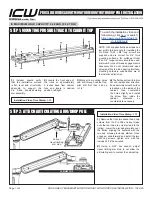
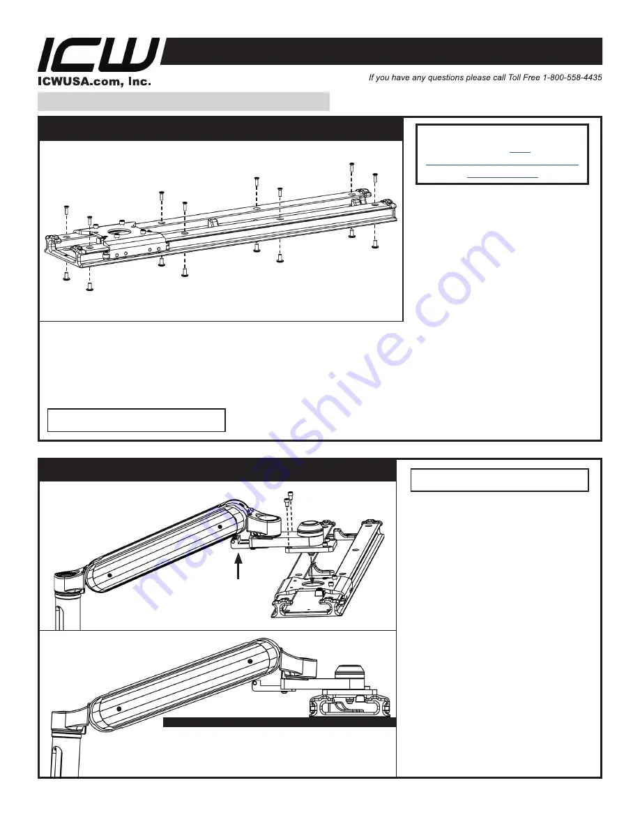
STEP 1: MOUNTING PROSLIDE TRACK TO CABINET TOP
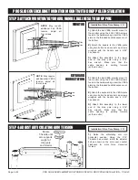
STEP 2: ATTACH ARTICULATING ARM/DROP POLE
1)
Installer should verify
that the installation surface
is flat, level and structurally
adequate to support the
Pro Slide track/articulating
arm assembly.
2)
Locate the front edge of
the track at approximately
9 inches back from cabinet
face and locate in desired
position, left/right.
3)
Mark all 8 mounting holes
and drill through cabinet top,
pilot drill first then drill up
to 1/4”.
4)
The flat head screw/furniture
nut can install either direction;
if an absolutely smooth surface
is desired on the inside of the
cabinet, then countersink
the holes slightly and install
the screw from inside the
cabinet, otherwise no
countersink is necessary.
NOTE: ICW supplies flat head screws and
low profile furniture nuts for installing the
Pro Slide. 10-24 x 5/8” long screws are
supplied and are correct for 3/4” thick
mounting surfaces, for surfaces thicker
than 3/4”, longer screws should be used,
minimum 5 turns of thread engagement is
necessary. We do not recommend wood
screws as this is a load bearing interface,
mounting hardware substitutions are at
the installer’s discretion.
1)
Remove the front two socket head cap
screws from the Pro Slide trolley (make
sure the rear two are only started into the
trolley). Lower the arm adapter plate over
the trolley, aligning the keyholes with the
two cap screws previously started. Once
engaged, slide forward and install the two
front cap screws, tighten all 4 with the
included 3/16” hex wrench.
2)
Using a 5/32” hex wrench, adjust
travel limiting arm stop to not allow the
articulating arm to contact the cabinet top.
Pull out
travel limiting
arm stop
CABINET TOP
Installation Video Time Stamp:
0:25

