TITAN ARM INSTALLATION
TITAN ARM INSTALLATION
T2 ARM INSTALLATION - rev 04/22/2014 pjm
Page 3 of 3
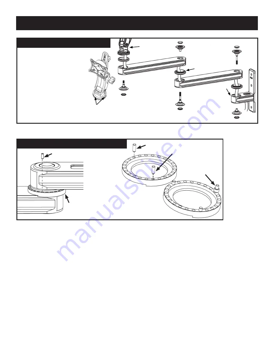
MANAGE CABLES THROUGH ARM
•
Using the Chrome 5mm hex key
provided, disassemble arm as shown
and lay out on a fl at surface.
•
Feed computer monitor cords and any
other cords through upper arm, lower
arm, wall mount and all bearings. When
feeding cords through arms, keep them
all to one side of bolts at arm joints.
•
Pass cords through slots in monitor
mount base plate and re-attach monitor
mount to front arm.
• Once all cords have been passed
through the arms, reattach arms in the
same order as they were disassembled
using the Chrome 5mm hex key.
• Torque bolts down to 204 in/lbs (17 ft/lbs)
Cable slots in
monitor mount
base plate
NOTE:
When measuring
for length of cords, be sure
to allow enough extra cord
to accommodate tilt and
rotation of monitor.
NOTE:
CORDS CAN BE
DAMAGED IF JOINTS
ARE ROTATED MORE
THAN 360 DEGREES.
Bearing
Wall mount
Paralink
WARNING:
When
disassembling the arms,
the Chrome 5mm hex
key must be used. If a
smaller hex key is used,
the bolt will strip.
ADJUST ROTATION LIMITS - WALL MOUNT
The rotation limits for
the arm are set by
placing the stop pins in
the hole corresponding
to where you want
the arm to stop. The
stop pin then collides
with the stop screw
under the wall mount
ear, stopping the arm.
The stop pins can be
removed and set by
hand.
Stop Pin
Stop Pin
Rotation
Limiter
Ring
Stop Screw
(under wall ear)
Stop Pin


