ULTRA 180 & 182 ARM INSTALLATION - 6/29/20
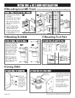
ATTACH FLIP UP
• Remove screws from
drop extension using
5/32” hex key.
• Align holes in keyboard
tray with screw holes in
drop extension.
• Attach keyboard tray using
the provided screws.
• If keyboard will not remain in vertical
position, tighten two button head
screws underneath fl ip up connector.
Page 3 of 4
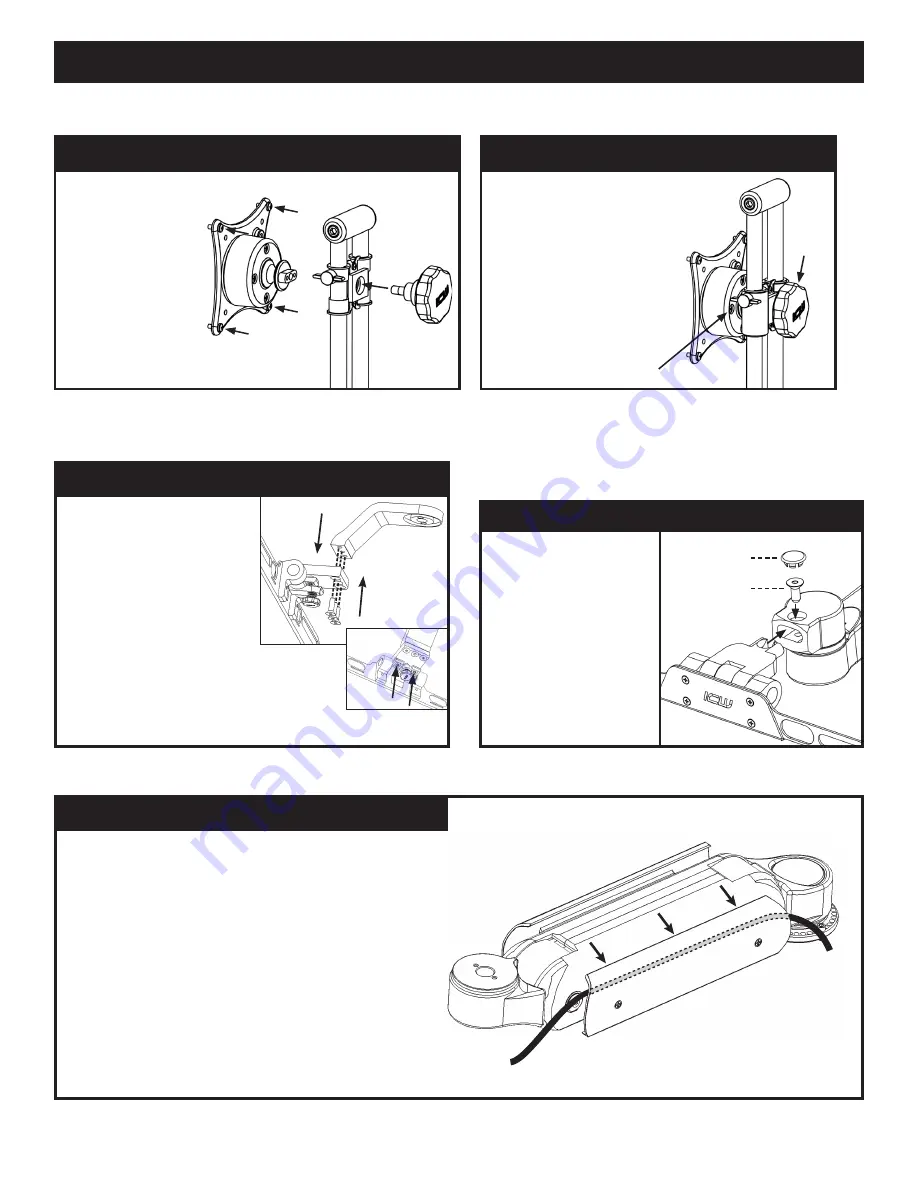
If Using EV710
ULTRA 180 & 182 ARM INSTALLATION
If Attaching To Ultra Flip-Up
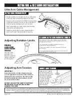
Ultra 180 & 182 Arm Cable Management
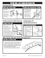
If Attaching To
Quick Disconnnect
Pivot tension adjustment screws
Slider
knob
RUN CABLES THROUGH ARM
• Cover plate is spring loaded. Loosen cover plate screws
on side of arm just enough to fit cables through gap.
• Run cables loosely between cover plate and arm.
Cables can be run on either or both sides of the arm.
• Push cover plate against arm and tighten screws,
being careful not to pinch cables.
• After installing cable, pull cable back and forth a
couple inches to confirm cables are not pinched.
• Remove screws from
drop extension using
5/32” hex key.
• Align holes in keyboard
tray with screw holes
in drop extension.
• Attach keyboard tray
using the provided screws.
• If keyboard will not remain in vertical
position, tighten the two button head
screws underneath flip-up connector
to adjust the flip-up’s tension.
ATTACH FLIP-UP TRAY
MOUNT WALL PLATE TO WALL
ADJUST BALL VESA HEIGHT & TENSION
• To adjust the height of
monitor, loosen slider
knob, position monitor
height on slider rails
then tighten knob.
• To adjust pivot tension,
gently and evenly
tighten or loosen the
four screws on the
back of the ball VESA.
• Mount VESA assembly
to slide rails.
• Fasten slider knob
through rails and into
VESA assembly.
• Attach VESA to
monitor using four
4mm screws in the
hardware bag
ATTACH QUICK DISCONNECT
• Remove beauty cap
on Quick Disconnect
block.
• Remove screw using
3/16” hex key.
• Slide keyboard tray
into Quick Disconnect
block.
• Replace screw and
tighten.
• Replace beauty cap.
Beauty cap
Screw


