background image

ULTRA 180 ARM INSTALLATION - rev  04/09/14  pjm

Page 2 of 4

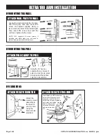
ATTACH WALL PLATE TO WALL

Locate the stud and mark the top hole, 

drill  11/64  pilot  hole  and  insert  #14 

screw  and  tighten  slightly.  Using  a 

level, mark the lower hole and drill pilot 

hole,  insert  #14  screw  and,  with  the 

unit level, tighten both screws.

NOTE:  ICW  supplies  #14  wood  screws.  If 

installing  onto  metal  studs,  you  will  need  to 

replace with proper metal stud fasteners.

W2

W3

IF MOUNTING TO A WALL

IF MOUNTING TO A POLE

IF USING EV65

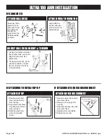
ATTACH VESA TO MONITOR

Attach the 

monitor mount 

assembly to 

the back of 

your monitor, 

using the 

4mm screws 

provided.

ATTACH VESA TO EV65 JOINT

Socket

cap screw

VESA

plate

Insert stubs on VESA plate into 

holes in the Ergovision joint 

assembly. Insert 5/16 x 3/4 

socket cap screws provided in 

both sides and tighten. Use the 

handle under mount

to loosen tilt friction

and adjust monitor

tilt.

ULTRA 180 ARM INSTALLATION

ATTACH POLE CLAMP TO POLE

Using the 1/4” hex key, 

separate the two halves of 

pole mount as shown, place 

around pole at the desired 

height and reassemble.

Summary of Contents for ULTRA 180

Page 1: ...lastic cover Insert Slider into Wall Track as shown at left and replace the small socket head cap screw and plastic cover ATTACH SLIDER TO ULTRA TRACK Once you have adjusted the slider to the desired height tighten down the Track Slider using the handle on the slider as shown Once tight make sure the handle is positioned so that it is pointing down as far as possible Pull and turn handle to positi...

Page 2: ... W3 IF MOUNTING TO A WALL IF MOUNTING TO A POLE IF USING EV65 ATTACH VESA TO MONITOR Attach the monitor mount assembly to the back of your monitor using the 4mm screws provided ATTACH VESA TO EV65 JOINT Socket cap screw VESA plate Insert stubs on VESA plate into holes in the Ergovision joint assembly Insert 5 16 x 3 4 socket cap screws provided in both sides and tighten Use the handle under mount ...

Page 3: ... 16 hex key 3 Slide keyboard tray into quick disconnect block 4 Replace screw and tighten 5 Replace beauty cap Beauty cap Screw ATTACH BALL VESA Mount the VESA assembly to the slide rails Screw the slider knob through the rails and into the VESA assembly as shown ATTACH VESA TO MONITOR Attach VESA to monitor using four 4mm screws in the hardware bag ADJUST BALL VESA HEIGHT TENSION 1 To adjust the ...

Page 4: ...hem near cavity of arm and bundling together if necessary 2 Remove cover by unscrewing four socket head cap screws Screws are captured by the cover so they cannot fall out Once screws are disengaged pull cover out of arm 3 Place cables within the channel Do not block the holes where screws will engage in arm 4 Replace cover and tighten screws Cables should be able to pull through to desired positi...

Reviews: