background image

ULTRA ARM INSTALLATION - 5/21/20

Page 3 of 4

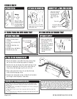
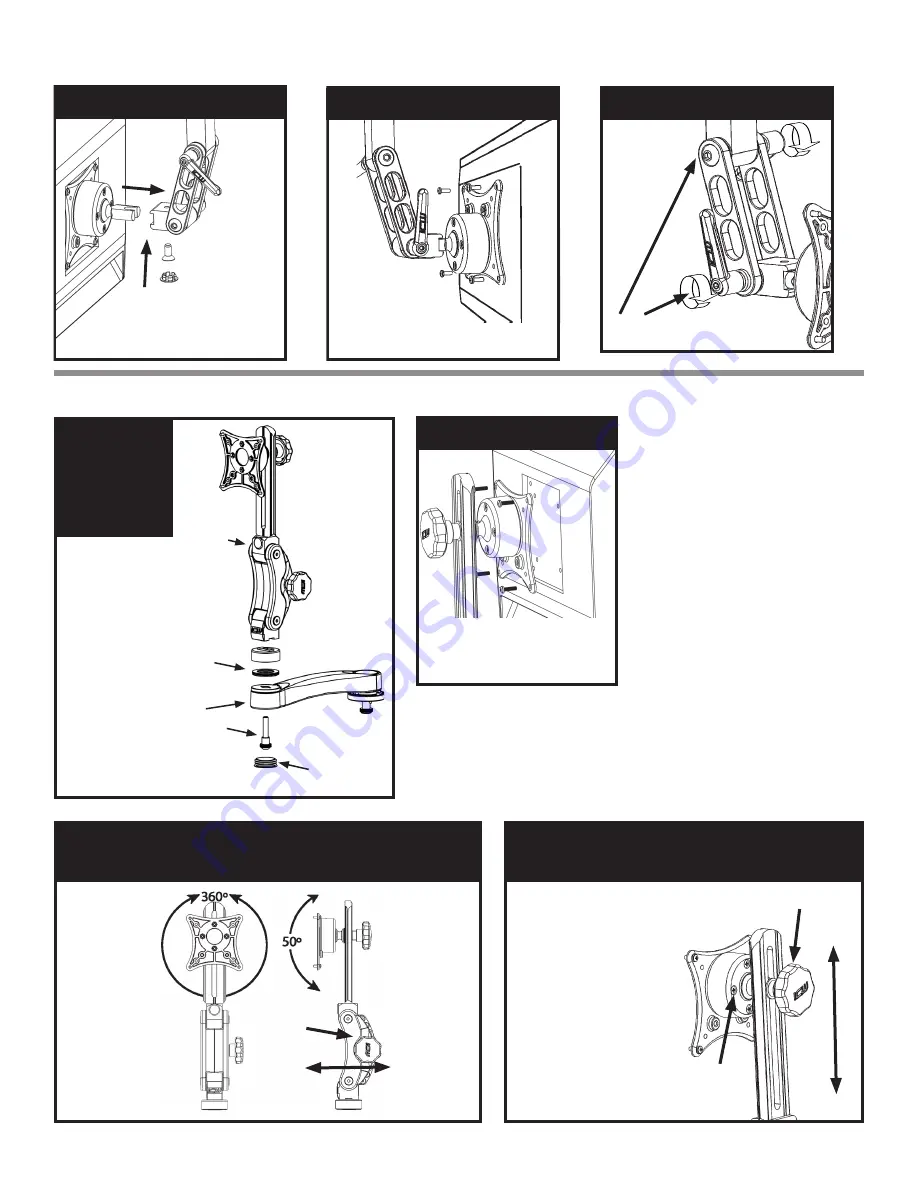
ATTACH VESA TO UL 500

Mount the

VESA assembly

to the friction

mount by sliding

the connecter into the UL500 

pivot block. Using the 5/32” hex 

key, secure fl at head screw back 

into place.

ATTACH VESA TO MONITOR

Attach the 

VESA plate to 

your monitor 

using the four 

4mm screws in 

the hardware bag.

ADJUST TILT HANDLES

Use the handles to adjust 

the tilt of the monitor.

IF USING UL550

IF USING UL500

ATTACH TO MONITOR

Attach your monitor to the VESA 

plate user the four 4mm screws in 

the hardware bag.

MONITOR TILT, ROTATION  

& ADJUST MONITOR DEPTH

MONITOR TILT 

& ROTATE

Gently hold sides 

of monitor. Tilt and 

rotate to desired 

position with ball 

VESA.

ADJUST 

MONITOR 

DEPTH


Loosen the 

adjustment 

knob, move 

the Paralink 

forward or 

back, then 

re-tighten 

the knob.

Adjustment 

Knob

Pivot tension 

adjustment 

screws

Use the slider knob to 

loosen the slider to adjust 

the height of the monitor 

on the Paralink.

Adjust the pivot tension 

of the ball by gently and 

evenly tightening or 

loosening the four  

screws on the back  

of the ball VESA.

Slider knob

ADJUST BALL VESA  

TENSION & HEIGHT

ATTACH 

PARALINK  

TO W2,  

W3 OR W5

Attach to Paralink 

to Ultra arm using 

3/8 bolt assembly 

and 1.25” bearing 

assembly provided. 

Insert bolt assembly 

up through wall ear. 

Place 1.25” bearing 

assembly over bolt 

on the other side 

of wall ear. Place 

Paralink over bolt 

and bearing and turn 

bolt until Paralink is 

secure and smoothly 

turns against the 

bearing.

Paralink

1.25”  

ID bearing 

assembly

3/8 bolt 

assembly

W2

Beauty cap

Summary of Contents for ULTRA

Page 1: ... replace these with proper metal stud fasteners or the provided snap togglers All hardware used to secure track mount must have a proper countersunk head Desk Mount Part Number Stud Length Maximum Desk Thickness D0 3 50 2 47 D1 3 50 1 87 D3 5 50 1 87 D5 7 50 1 87 D7 10 50 2 38 Drill a 3 8 hole through the horizontal mounting surface Screw stud into base of desk mount Push the stud on the desk moun...

Page 2: ...evel tighten both screws NOTE ICW supplies 14 wood screws If installing onto metal studs you will need to replace with proper metal stud fasteners W3 UL510 Paralink Beauty cap Beauty cap 1 25 ID bearing assembly 1 25 ID bearing assembly 3 8 bolt assembly with 3 8 ID bearing 3 8 bolt assembly with 3 8 ID bearing W2 W2 ATTACH UL500 TO W2 W3 OR W5 Attach to UL500 to W2 wall mount using 3 8 bolt assem...

Page 3: ...osition with ball VESA ADJUST MONITOR DEPTH Loosen the adjustment knob move the Paralink forward or back then re tighten the knob Adjustment Knob Pivot tension adjustment screws Use the slider knob to loosen the slider to adjust the height of the monitor on the Paralink Adjust the pivot tension of the ball by gently and evenly tightening or loosening the four screws on the back of the ball VESA Sl...

Page 4: ...on 3 Attach keyboard tray using the provided screws ATTACH PARALINK 1 Remove beauty cap on Paralink 2 Remove screw using 3 16 hex key 3 Slide keyboard tray into Paralink 4 Replace screw and tighten 5 Replace beauty cap Beauty cap Screw NOTICE ICWUSA COM Inc provides the appropriate hardware fasteners to match the majority if not all standard monitors and devices It is the responsibility of the ins...

Reviews: