ULTRA ARM INSTALLATION - 5/21/20
Page 4 of 4
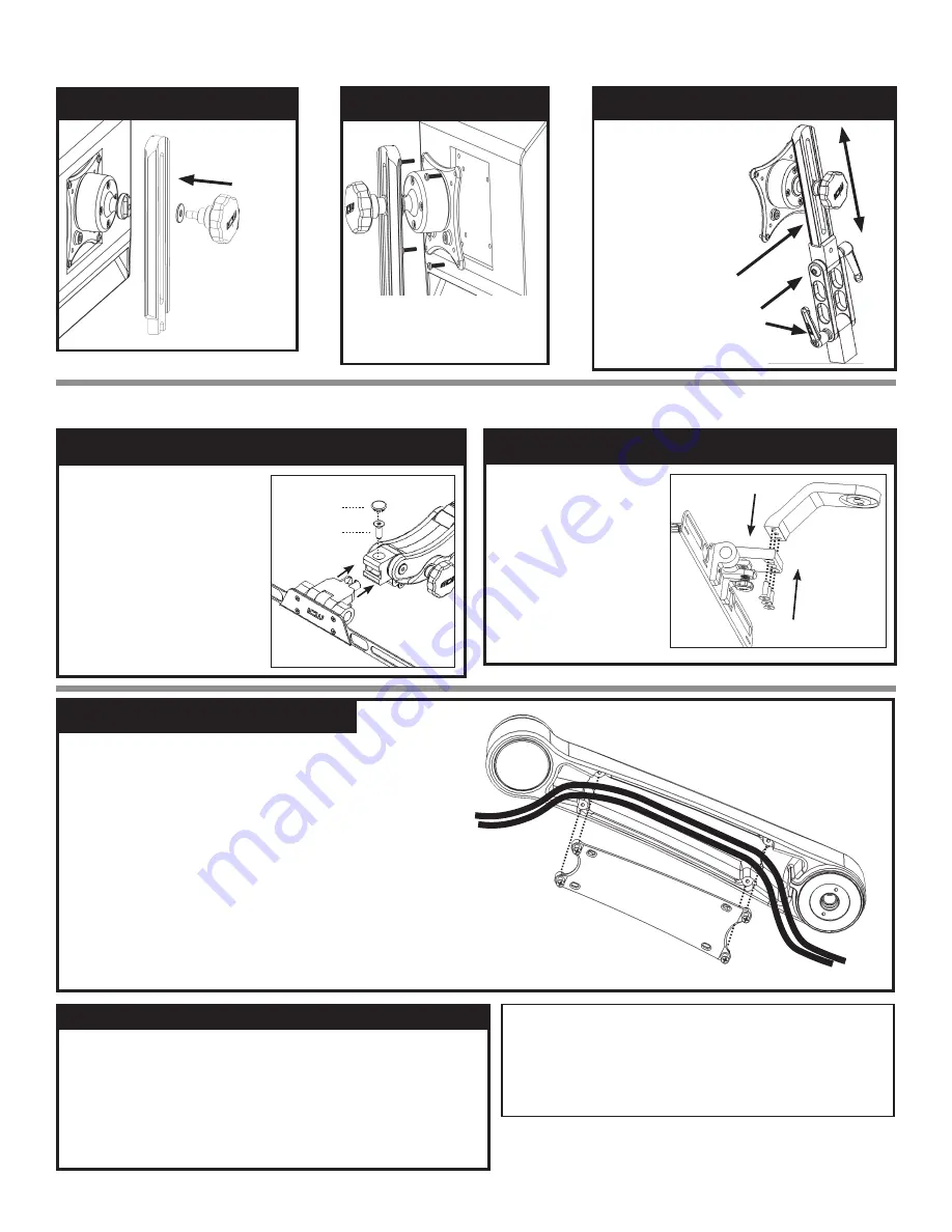
ULTRA CORD MANAGEMENT
1. Prepare all cables to route within the arm by placing them
near cavity of arm and bundling together if necessary.
2. Remove cover by unscrewing four socket head cap screws.
Screws are captured by the cover so they cannot fall out.
Once screws are disengaged, pull cover out of arm.
3. Place cables within the channel. Do not block the holes
where screws will engage in arm.
4. Replace cover and tighten screws. Cables should be able to
pull through to desired position if necessary.
IF USING PARALINK KEYBOARD TRAY
IF USING ULTRA KEYBOARD TRAY
IF USING UL510
ADJUST TILT & MONITOR HEIGHT
Use the handles to
adjust the tilt of the
monitor.
Adjust the height of
the monitor along
the rails of the 510.
Then tighten in
place using slider
knob.
Slider Knob
ATTACH VESA
Mount the VESA
assembly to the slide
rail by screwing in
the knob through the
rail into the VESA
assembly as shown.
ATTACH TO MONITOR
Attach your monitor to the VESA
plate user the four 4mm screws in
the hardware bag.
ATTACH FLIP UP
1. Remove screws from
drop extension using
5/32” hex key.
2. Align holes in keyboard
tray with screw holes in
drop extension.
3. Attach keyboard tray
using the provided
screws.
ATTACH PARALINK
1. Remove beauty cap on
Paralink.
2. Remove screw using 3/16”
hex key.
3. Slide keyboard tray into
Paralink.
4. Replace screw and tighten.
5. Replace beauty cap.
Beauty cap
Screw
NOTICE: ICWUSA.COM, Inc. provides the appropriate hardware fasteners to
match the majority if not all standard monitors and devices. It is the responsibility
of the installer / integrator to ensure that the screws and fasteners have the
adequate thread engagement. The rule of thumb is that the thread depth is greater
than the diameter of the hole or 4 full turns of 360 degrees of thread engagement.
It is also the responsibility of the installer / integrator to ensure that they do not
damage the monitor or device by using a screw or fastener that is too long for hole
and therefore damaging the unit by inserting too far.
When cleaning your ICW mounting unit please follow the points below. Proper
cleaning of the mounting device will help assure proper function and extend the
life of the unit.
1. Any general cleaner is acceptable except degreasers are not recommended near
the bearing entrances.
2. Spray cleaner or water on a soft cloth or paper towel and then wipe down
the mounts.
3. Do not spray directly at the bearing seams (located at all swivel points) as this could
reduce the life of the bearings.
CLEANING OF THE ICW MOUNTING DEVICE


