ELITE 5120 InsTaLLaTIon
ELITE 5120 INSTALLATION - rev 12/22/15 pjm
If you have any questions please call Toll Free 1-800-558-4435
ICWUSA.com, Inc.
Page 1 of 3
Instructions for All Configurations
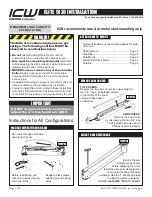
Do not use power tools to assemble or
adjust the arm. Use hand tools onLY.
IMPoRTanT
ICW recommends wood or metal stud mounting only.
MAXIMUM LOAD CAPACITY:
28 Lbs (12.7 kg)
•
Do not
attempt to adjust the Elite arm until all
components are mounted (monitor, keyboard, etc.)
•
Arm must be completely horizontal
(extended)
before adjusting the arm’s tension. Failure to do so will
damage the arm and void the warranty.
•
never loosen or remove any of the shoulder
bolts.
Doing so will cause the arm to immediately
come apart with tremendous force, and could cause
serious injury.
•
If equipment requiring AC power is mounted to this unit,
have a certified electrician inspect the installation.
•
Failure to install this unit according to these instructions
will void all ICW warranties. If installed incorrectly, ICW
is not liable for any damage or injury caused by the unit.
the elite arm contains high pressure gas
springs. the following cautions MUSt be
observed to avoid serious injury.
DanGER!
Follow instructions on the following pages for style
of mount.
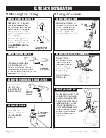
Ceiling Mount.............................................. Page 2
Quicklink ..................................................... Page 2
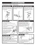
Pole Mount ................................................. Page 3
Wall & Wall Track Mount ............................. Page 3
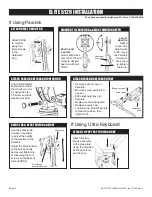
Paralink....................................................... Page 4
aTTaCH aRM To MoUnT
REMoVE aRM CoVERs
TOP COVERs:
Remove the long arm covers by unscrewing the
two 1/4” long 6-32 flathead screws
in the center of the cover
using a Phillips head
screwdriver.
END COVERs:
Remove the end covers
by unscrewing the two 3/4” long
10-24 flathead screws using a
Phillips head screwdriver.
MOUNT
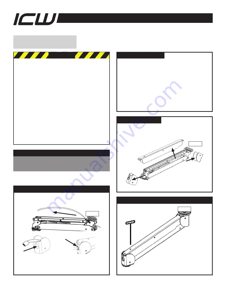
aDJUsT aRM REsIsTanCE
MOUNT
Extend the arm
straight out as shown
before adjusting the arm’s
resistance. Be sure all equipment
is mounted on the arm before
adjusting. Use the T-handle provided
to adjust the arm’s resistance.
DO NOT UsE POWER TOOLs TO ADjUsT.
ManaGE WIREs THRoUGH aRM
MOUNT
Run wires through end frame
and along channel.
Before reattaching arm
covers, slip wires through
end cover ports.
Reattach black plastic
bushing around exiting
wires.


