ELITE 5120 INSTALLATION - rev 12/22/15 pjm
ELITE 5120 InsTaLLaTIon
Page 2 of 3
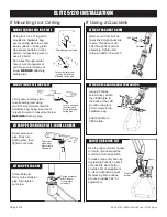
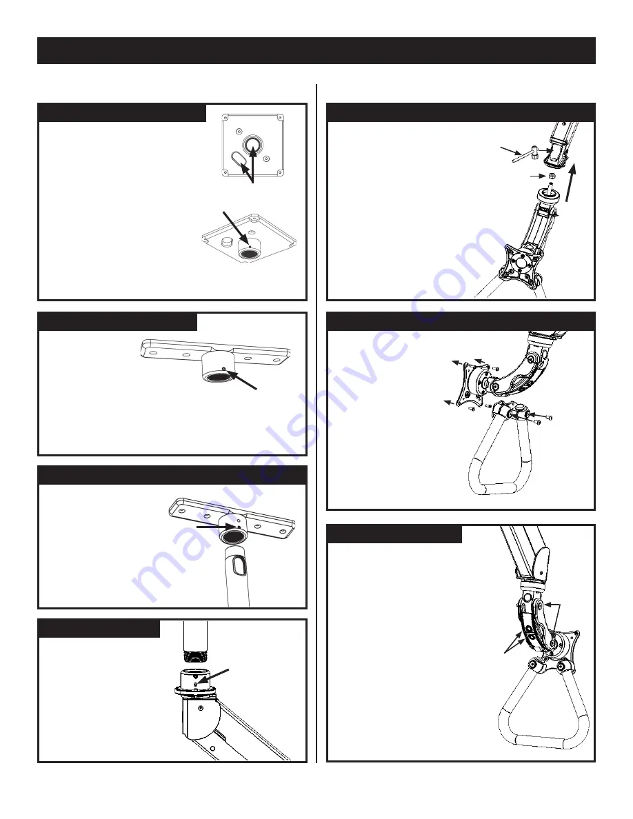
If Mounting to a Ceiling
If Using a Quicklink
MoUnT InLInE CEILInG PLaTE
Firmly secure ceiling plate
to solid ceiling joist using
four #14 wood screws found in
hardware bag, being sure mount
is level. Be sure to loosen set screw
BeFore
attaching pipe.
Loosen set screw
in ceiling plate
before attaching
ceiling pipe.
MoUnT sQUaRE CEILInG PLaTE
Loosen the set screw
in ceiling plate before
attaching ceiling pipe.
Using four 1/4 x 2” lag bolts
provided in hardware bag,
secure ceiling plate to a solid
wood surface or ceiling joist.
Use square pattern or inline
pattern, always being sure to
use all 4 bolts.
Run wires through center
hole or wire management
port. Be sure to loosen set
screw
BeFore
attaching
ceiling pipe.
Wire management holes
aTTaCH PIPE To CEILInG PLaTE - InLInE & sQUaRE
Screw extension
pipe firmly into
ceiling plate, then
tighten set screw.
Tighten set
screw after
pipe is tightly
screwed in.
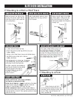
aTTaCH PIPE To aRM
Screw Elite arm
firmly onto extension
pipe, then tighten
set screw.
Tighten set screw
after Elite arm
is completely
screwed in.
aTTaCH VEsa anD HanDLE To MonIToR
Using a Phillips
screw driver, attach
the VESA plate to
the back of the LCD
monitor using four
4mm screws in the
hardware bag.
Attach handle to
VESA plate.
aTTaCH PaRaLInK To aRM
9/16 wrench
Nut
Remove nut from bolt on
Quicklink. Attach Quicklink
to arm. Thread nut onto
bolt through front of arm
assembly. Tighten bolt
with provided 9/16 wrench.
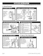
aDJUsT QUICKLInK TILT
Quicklink
buttons
Pivots
Use the under-monitor handle
to rotate, tilt and swivel the
monitor to desired position.
Increase range of motion by
depressing buttons on back
of Quicklink. Each button
provides 90° of adjustment
for its corresponding pivot.
Depressing both buttons
at once provides 180° of
adjustment.


