background image

English

6

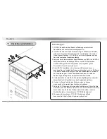
1. ICY DOCK reserves the right to change or to upgrade any technical 

    specifications  without prior notice.

2. ICY DOCK will not be liable for any software, hardware, and/or stored 

    data that may be become damaged or dysfunctional through the usage 

    of our product. ICY DOCK will only be responsible for repairing and 

    servicing its own product.

3. Due to specification differences between SATA I and SATA II hard drives, 

    the LED will only work with SATA II hard drives. To enable the 

    enclosure’s LED with SATA I hard drives, please refer to Note 4.

4. To allow the enclosure’s LED to work with SATA I hard drives, you will 

    need an optional HDD Access cable. Please connect the Access signal 

    pins provided on the backplane of the enclosure to the respective Host 

    Port’s Access signal pins. Please refer to your host port’s instruction 

    manual to locate its Access signal pins.

5. To determine if SATA II hard drives have built in HDD Access signal, 

    please refer  to your HDD manufacture specifications.

6. To perform hot-swap function, the host side must also support hot-swap.

7. In the event that the LCD is not functioning properly, please reset the 

    LCD. If the problem persists, please contact the nearest ICY DOCK 

    support center.

8. For any further inquiries about ICY DOCK product or related product 
    information, please visit http://www.icydock.com.

Note:

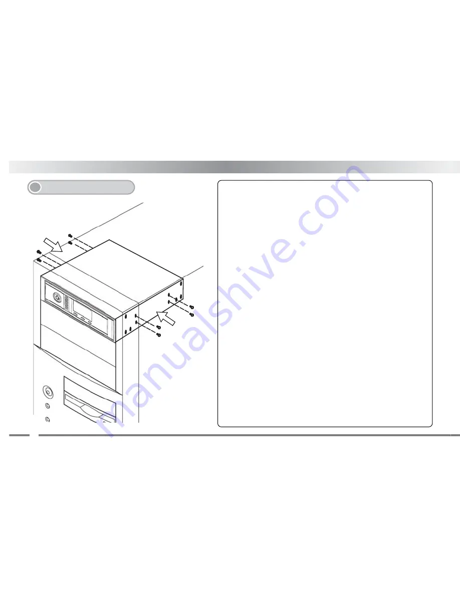
Device Installation

7.

Summary of Contents for MB672SKGF

Page 1: ...MB672SKGF Screw less Internal 3 5 SATA Enclosure w LCD User Manual...

Page 2: ......

Page 3: ......

Page 4: ...f LCD screen does not return to Main Display stop operation for 15 seconds the LCD will then automatically return to the Main Display and the original tempera ture detection setting will be cancelled...

Page 5: ...the following 4 6 Fan Fail Alarm HDD access and Fan signals are displayed Temperature and alarm buzzer signals will continuously flash Original detection set at 50 0 122 0 if temperature detected over...

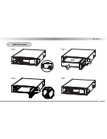
Page 6: ...English 5 PULL HDD A B STEP 1 STEP 2 STEP 3 STEP 4 HDD Installation 6...

Page 7: ...work with SATA I hard drives you will need an optional HDD Access cable Please connect the Access signal pins provided on the backplane of the enclosure to the respective Host Port s Access signal pi...

Page 8: ...Espa ol Contenidos de la caja 1 7 Descripci n del panel frontal 2 Abierto Bloqueo Paso 3...

Page 9: ...e d a 14 Selector FIJAR 15 Indicador HUTR Nota HUTR HDD Usage Time Record Registro de tiempo de uso de disco duro Elemento Configuraci n predeterminada Detecci n de temperatura 50 0 122 0 Pantalla MAE...

Page 10: ...ncipal detenga el uso durante 15 segundos La pantalla LCD volver entonces autom ticamente a la pantalla principal y se cancelar la detecci n de temperatura original Configuraci n predeterminada 50 0 1...

Page 11: ...rma de fallo de ventilador Se mostrar n las se ales de acceso al HDD y al Ventilador Las se ales de temperatura y zumbador dealarma parpadear n continuamente La detecci n original est fijada a 50 0 12...

Page 12: ...Espa ol 11 TIRAR HDD A B STEP 1 STEP 2 STEP 3 STEP 4 Instalaci n de HDD 6...

Page 13: ...opcional a disco duro Conecte los terminales de se al de acceso suministrados al panel posterior de la carcasa y a los terminales de se al de acceso respectivos del puerto del equipo Consulte el manu...

Page 14: ...Deutsch 13 Packungsinhalt 1 OPEN LOCK Step 3 Vorderseite 2 Bedienungsanleitung...

Page 15: ...gesanzeige 14 Auswahlanzeige 15 HUTR Anzeige Anmerkung HUTR HDD Usage Time Record Betriebsstunden der Festplatte Position Voreinstellungen Warntemperatur 50 0 122 0 MASTER SLAVE Betriebsart SLAVE HUTR...

Page 16: ...m zur ckkehren t tigen Sie f r 15 sec keine Eingaben Daraufhin kehrt das Ger t automatisch auf den Startbildschirm zur ck und die Grundeinstellungen werden entsprechend ge ndert Voreinstellung 50 0 12...

Page 17: ...ezeigt 4 6 Warnung bei L fterfehler Symbol f r Festplattenzugriff und L ftersignal werden dargestellt Temperatur und Alarmglocke leuchten st ndig Bei berschreitung der eingestellten Warntemperatur Bei...

Page 18: ...Deutsch 17 PULL HDD A B STEP 1 STEP 2 STEP 3 STEP 4 HDD Installation 6...

Page 19: ...ben tigen Sie ein Zusatzkabel Dieses wird ben tigt um die LED Signal Pins des Produktes mit den Signal Pins des Mainboards zu verbinden Zur Lokalisierung der Pins auf dem Mainboard lesen Sie bitte die...

Page 20: ...650104 2007 VER 1 0...

Reviews: