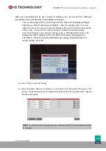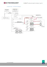
ClearMark™
Installation, Operation & User Manual
–
Page 110
V 1.S.10 January 2021
V-1.S.1
Internal Jumpers
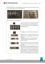
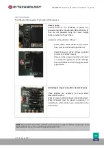
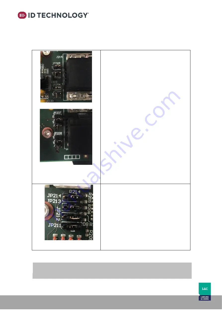
The following table explains the function of the jumpers:
Power supply:
Junction Box has the possibility to power the
connected printers through each DB15HD cable. (if
they are not powered using the Power Supply
(brick) provided with each head.
Jumpers must be placed as follows::
-
JP205, JP206, JP207, JP208: common GND.
They must be connected in position 1-2.
-
JP201 (Printer 1), JP202 (Printer 2), JP203
(Printer 3), JP204 (Printer 4):
-
Place each the jumper in position 1-2 only if
it is desired to power the printer through
the Junction Box and not through its power
supply brick.
Alarm Signal - Signal out_noError (alarm beacon)
These jumpers are necessary to ensure alarm
beacon will function.
JP211 (Printer1), JP212 (Printer2), JP213 (Printer3),
JP214 (Printer4) must be placed in position 1-2
according to which printers are connected to the
Junction Box
NOTE
: Never power the printers with the external power supply brick if the junction box power
supply jumpers are set to power the heads (position 1-2).


