background image

3 Installation 

Thermal Imaging Integrated Network Camera   

User Manual


Issue  V1.0  (2014-01-10) 


Installation 

3.1 Preparations 

You may need the tools and accessories shown in Table 3-1 during the installation (you 
need to prepare the tools by yourself, and the accessories are in the package of the 
camera). 

Table 3-1


Installation tools 

Tools 

Appearance 

Phillips screwdriver (prepare by yourself) 


Claw hammer (prepare by yourself) 


Hammer drill (prepare by yourself) 


Spirit level (prepare by yourself) 


T15 ring spanner (delivered with the 
camera) 


Stainless hexagon socket head cap screw 
(delivered with the camera) 


Self-tapping screw (delivered with the 
camera) 


Inflatable colloidal particle (delivered with 
the camera) 


Summary of Contents for IV-THM42F25

Page 1: ...Thermal Imaging Integrated Network Camera User Manual IV THM42F25 12000 Ford Suite110 Dallas TX 75234 Tel 972 247 1203 Fax 972 247 1291 www idview com...

Page 2: ......

Page 3: ...wing symbols whose meanings are described accordingly Symbol Description It alerts you to fatal dangers which if not avoided may cause deaths or severe injuries It alerts you to moderate dangers which...

Page 4: ...etector in the thermal imaging camera may be permanently damaged If this device is installed in places where thunder and lightning frequently occur ground the device nearby to discharge high energy su...

Page 5: ...ce away from heat sources such as radiators electric heaters or other heat equipment Keep the device away from moist dusty extremely hot or cold places or places with strong electric radiation If the...

Page 6: ...ation Mode 7 3 3 Installation Procedure 7 4 Quick Configuration 11 4 1 Login and Logout 11 4 2 Main page layout 12 4 3 Browsing Video 13 4 3 2 Download the right control in the Internet Explorer 15 4...

Page 7: ...t It can clearly detect and find the target as well as identify the camouflaged and hidden target in both day and night Therefore it achieves real 24 hour surveillance Monitoring the temperature field...

Page 8: ...VOUT It outputs the analog video signals and can be connected to the TV monitor to view analog videos 4 SD card indicator The SD indicator has the following states OFF The SD card is not inserted ON...

Page 9: ...tion cable Table 1 2 Multi connector combination cable ID Core of Cable Functions Connection 1 Orange Alarm output 1 negative Connects to the alarm output device White injected with black Alarm output...

Page 10: ...upporting pseudo color mode switching black hot white hot rainbow ironbow Supporting the DVE image enhancement Supporting noise reduction and mirroring Supporting four coding algorithms that is H 264...

Page 11: ...g Integrated Network Camera User Manual 2 Device Dimensions Issue V1 0 2014 01 10 5 2 Device Dimensions Figure 2 1 shows the dimensions of the thermal imaging integrated network camera Figure 2 1 Dime...

Page 12: ...and the accessories are in the package of the camera Table 3 1 Installation tools Tools Appearance Phillips screwdriver prepare by yourself Claw hammer prepare by yourself Hammer drill prepare by you...

Page 13: ...the support and the camera 3 3 Installation Procedure Step 1 Remove the installation location labels delivered with the camera Stick the installation location labels on the ceiling or the wall as sho...

Page 14: ...ang the integrated camera into the base along the guide slots and rotate it to a certain angle to facilitate cable connection as shown in Figure 3 3 Figure 3 3 Hanging the integrated camera into the b...

Page 15: ...tep 6 Fix the integrated camera to the installation base as shown in Figure 3 5 Figure 3 5 Fixing the integrated camera to the installation base Step 7 Align the focusing fixture at the lens grooves c...

Page 16: ...the screws Figure 3 7 Adjusting the surveillance angle 1 Loosen the screws 1 and adjust the part 1 along the arrow direction The adjustment angle is 360 degrees 1 Loosen the screws 2 and adjust the p...

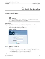
Page 17: ...Login system Step 1 Open the Internet Explorer enter the IP address of IP camera default value 192 168 0 120 in the address box and press Enter The login page is displayed as shown in Figure 4 1 Figur...

Page 18: ...ntrol PTZ Configure and log out of the system Figure 4 2 is shown the main page layout Table 4 1 lists the elements on the main page layout Figure 4 2 Main page layout Table 4 1 Elements on the main p...

Page 19: ...the following operation in this area Add delete and invoke the presents and tacks Adjust the PTZ rotation speed Enable or disable 3D position Set the direction to due north Set the PTZ timer NOTE PTZ...

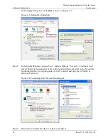
Page 20: ...d site Step 2 In the Internet Explorer choose Tool Internet Options Security Customer level and set Download unsigned ActiveX control and initialize and script ActiveX controls not marked as safe for...

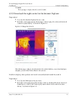
Page 21: ...with ActiveX control to reduce latency as shown in Figure 4 5 Figure 4 5 Change the ActiveX Click the message jump to download ActiveX control interface once downloading is complete you can watch more...

Page 22: ...download the latest version of Flash Play live video jump to download ActiveX control interface once downloading is complete you can watch more fluent video screen 4 3 3 In the Google Firefox or Safa...

Page 23: ...er Procedure Step 1 Choose Device Configuration Local Network The Local Network page is displayed as shown in Figure 4 7 Figure 4 7 Local Network page Step 2 Set the parameters according to Table 4 2...

Page 24: ...fault Gateway This parameter must be set if the client accesses the device through a gateway Setting method Enter a value manually Default value 192 168 0 1 Preferred DNS Server IP address of a DNS se...

Page 25: ...ick Configuration Issue V1 0 2014 01 10 19 If you set only the Subnet Mask Default Gateway Preferred DNS Server and Alternate DNS Server parameters you do not need to log in to the system again You ca...

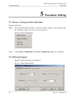
Page 26: ...e Step 1 On the Internet Explorer interface or the client software interface select and right click the surveillance image to the set as shown in Figure 5 1 Figure 5 1 Sensor configuration Step 2 Choo...

Page 27: ...the lighter one are reversed Other modes include rainbow and ironbow How to set Select from the drop down list box Default value White hot Dynamic DVE The sharpness of normal thermographic images is l...

Page 28: ...erface Table 5 2 Parameters on the FFC mode interface Parameter Description Setting FFC Mode The internal of the thermal imaging camera may comprise the mechanical action correction mechanism that can...

Page 29: ...nges when the camera is powered on The FFC is relatively frequent which is normal Manual In the manual FFC mode the camera does not automatically perform the FFC based on the temperature change or the...

Page 30: ...FFC based on the temperature change or the specified period You can press the Do FFC button 5 4 DNR Figure 5 4 shows the DNR interface Figure 5 4 DNR interface Table 5 3 lists the DNR parameters Tabl...

Page 31: ...Network Camera User Manual 5 Parameter Setting Issue V1 0 2014 01 10 25 5 5 Lens Control Figure 5 5 shows the lens control interface Figure 5 5 Lens control interface The electrical focusing lens can...

Page 32: ...el 420x315 Pixel spacing 25 um Response waveband 8 14 um Thermal sensitivity NETD 50 mK Frame frequency 50 60 Hz Video features Prime lens 8 15 25 35 50mm optional Focusing mode Manual Field angle 75...

Page 33: ...d SIP Storage communication protocol CIFS and NFS WEB management Embedded WEB service remote browsing and configuration over IE browser Remote upgrade and maintenance Support Integration Supporting th...

Page 34: ...figurable size Character display Time date channel No channel name and user defined characters Security Password protection multi level user group management user define permissions and one key reset...

Page 35: ...rs PBDE Structural part Board circuit module Cable connector Accessories indicates that the concentration of the hazardous substance in all homogeneous substances of the component is within the limit...

Reviews: