Patent No. US 8,856,780 CA 2759622
AUTOMATIC
TRANSMISSION
CUT LOOP
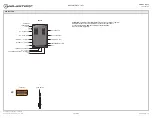
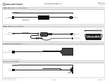
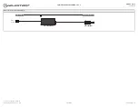
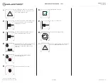
BOX CONTENTS
NC - 4 PIN RED
TELEMATIC 2 - 4 PIN RED
TELEMATIC 1 - 4 PIN BLUE
2 PIN BLACK - LED
PROGRAMMING BUTTON
THERMISTOR - 2 PIN BLUE
LED 1
LED 2
RF PORT/WEBLINK PORT - 4 PIN BLACK
USB
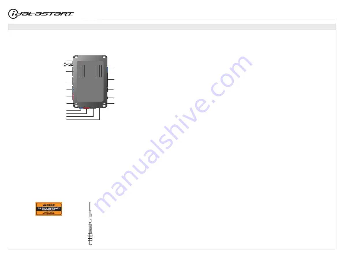
HOOD SWITCH
STICKERS
MODULE
M3 - 10 PIN WHITE
M2 - 12 PIN BLACK
M5 - 6 PIN BLUE
M4 - 20 PIN BLACK
2X
BOX CONTENTS - 1 OF 1
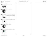
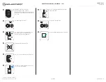
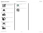
ATTENTION: To complete this installation some accessories may be required.
Visit our website to see all the required accessories for your vehicle.
Use the T-harness ADS-THR-xxx to complete the installation.
Accessories sold separately.
www.idatalink.com
Automotive Data Solutions Inc. © 2019
CMVWXA0
PAGE 3 OF 12
• 20190702