Installation Manual.
Touchscreen Terminal. Rev 1.03 November 2009
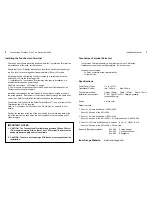
Touchscreen Terminals provide an intuitive, user friendly touchscreen interface with
colour backlit display and plain english prompts for operations such as:
-Arming/disarming the system and isolating/de-isolating zones.
-Viewing and acknowledging alarms.
-Viewing area and system status, event messages and the historical event log.
-Building/home automation control and timing operations.
The unit has an elegant, slimline housing available in charcoal or ivory and a
customisable architectural face plate. Installation is simplified with screw terminals
for LAN wiring while the tamper switch is integrated into the PCB and housing
design. The module number is preset to 01 at the factory, but can easily be altered
from the Touchscreen if multiple units are connected to the same Control Module.
No physical Auxiliaries are available, but 32 Auxes are provided for Beeper/Backlight
control & logic operations. X04=Pulse beep / X05=Cont. beep / X06=Backlight on.
Programming options allow the installer to define appropriate settings for each
Touchscreen used in the system. e.g. The Areas and Diary messages to be displayed,
operations allowed, and which of those operations require the user to ‘log in’ with a
PIN code. This allows each Touchscreen to provide access to relevant functionality.
Three default display layouts are currently available, each with 2 or more screens in
addition to the main menu screen.
See page 7 for details.
Insight V4.1 or later; or WDirect software V6.0 or later can be used to tailor the
screen layouts to system requirements. Layouts can be edited and/or added via the
Layout Editor accessible from the Touchscreen Terminal programming window.
Compatability:
Control Module F’ware: Must be V6.0 (or V5.8Beta) or later.
Insight Software:
Must be V3.2 or later. V4.1 or later if Edit layouts required
WDirect Software:
Must be V6 or later.
Concept 4000
Touchscreen Terminal
995022 (Ivory) / 995022CH (Charcoal)
1
8
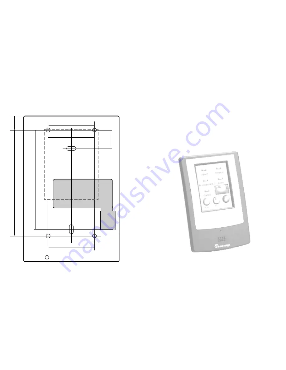
Backplate Installation Template
Due to on-going development this manual is subject to change without notice.
© 2007 - 2009. Inner Range Pty. Ltd.
Part No: 635022
24 mm
24 mm
15 mm
= Mounting hole locations
Position of
LCD Display
48 mm
1
10 mm
24 mm
24 mm
48 mm
19 mm
103 mm
Cable entry cutout
84 mm. * See Note.
*
Note:
Elongated mounting holes dimensioned to suit
s
tandard electrical plasterboard mounting clip.


