background image

Subject to technical changes | Valid from January 2021    

2

Information on this Operating Manual

Operating Manual and Installation Guide

This Operating Manual applies to all built-in units of the Caleo Hot/Neutral type of self-service display cases, irrespective of the different 
possible configurations regarding freestanding display cases and Gastronorm dimensions. Built-in units must be covered before they 
are put into use keeping the technical requirements in mind. The possibilities described in this Operating Manual show the majority of 
configurations. Due to custom designs, many other configurations of the Caleo Hot/Neutral self-service display cases are still possible.

Copyright © December 2020, AKE Ausseer Kälte- und Edelstahltechnik GmbH. All rights reserved.
This documentation is the original documentation.
No part of this publication may be reproduced, stored, or transmitted and published in any form with any means without the 


prior written permission of AKE.

Document: 


Operating Manual_Caleo_Hot_Neutral 

Revision: 


21A

Valid from: 


January 2021

Summary of Contents for CALEO HOT

Page 1: ...Operating Manual CALEO HOT BASIC Translation of the original Self contained 21A ...

Page 2: ... keeping the technical requirements in mind The possibilities described in this Operating Manual show the majority of configurations Due to custom designs many other configurations of the Caleo Hot Neutral self service display cases are still possible Copyright December 2020 AKE Ausseer Kälte und Edelstahltechnik GmbH All rights reserved This documentation is the original documentation No part of ...

Page 3: ... 1 First steps 28 2 4 2 Drain connection 32 2 5 Malfunctions and causes 33 2 6 Status displays and error messages on the display 34 3 Operation Care 36 3 1 Initial start up 36 3 2 Operation of the units 37 3 2 1 Units with dry heat 37 3 2 2 Units with heating climate 39 3 3 Stocking the unit 41 3 4 Cleaning and care 42 3 4 1 Information on cleaning and testing 42 3 4 2 Cleaning intervals 43 3 4 3 ...

Page 4: ... unit put it into operation and operate it must have this document available and must have read and understood it The operator must check and ensure this Our unit requires correct installation start up operation and care Non compliance with the points mentioned above can lead to warranty guarantee and product liability exclusions but also to damage and safety hazards Always keep this document comp...

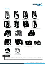
Page 5: ...has been set up NOTE Caleo Cold 60 80 120 142 Caleo Hot 60 80 120 142 Revisionsklappe Caleo Basic 60 80 120 Caleo Neutral 60 80 120 142 Against a wall Front side with Caleo module 142 Front side with refrigerated well with convection cooling and boards Front side with corner modules Four modules back to back Side by side Caleo Neutral Plus 60 80 120 142 Back to back Stand alone solution Corner mod...

Page 6: ... Caleo unrefrigerated corner module oblique Accessories Caleo product basket large with holder Caleo product basket small with holder Bumper in wood effect Cough and spit guard Chutes Please note that at least two persons are required to lift the unit and at least four persons are needed from a specific size 60 kg of the units Enlist the help of another person for spotting for the installation The...

Page 7: ...anual regarding the correct installation start up operation maintenance and assembly of the unit unauthorised mechanical or technical changes to the unit inadequate maintenance of used and wearing parts unauthorised repairs use of aggressive or caustic cleaning agents forces of nature or force majeure Also excluded from liability are breakage of glass breakage of plastic components seals or lighti...

Page 8: ... Kälte und Edelstahltechnik GmbH Pichl 66 A 8984 Bad Mitterndorf T 43 3624 21100 0 F 43 3624 21100 33 E office ake at When you contact our support department have the serial number of your unit ready This can be found on the rating plate or the AKE Certified plate see Chapter 1 7 NOTE If any malfunctions occur switch the unit off and immediately contact your supplier service partner or the manufac...

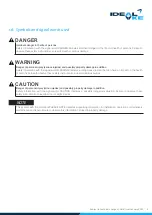
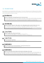
Page 9: ...s Failure to observe these safety instructions can lead to death or serious damage Danger of personal injury serious injuries and possibly property damage in addition Safety information with the signal word WARNING indicates a dangerous situation that can have an impact on the health of persons Failure to observe these safety instructions can lead to serious injuries DANGER WARNING Danger of perso...

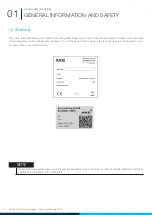
Page 10: ...g on the model the rating plate is located on the outer shell of the bottom tray on the front side see Chapter 2 1 or in the base on the housing of the technology box see Chapter 2 1 or in the base on the cover of the controller General technical specifications can be found in Chapter 2 2 Due to the large number of models additional technical specifications are stated on the rating plate NOTE ...

Page 11: ...only be replaced with original parts Do not store any combustible or explosive products in the unit or close to it During the assembly or installation the unit must be covered adequately so that no contact with live parts is possible The installation environment must be stable in order to withstand the stresses of everyday operation Steering and fixed position casters must be checked and set to a ...

Page 12: ...nits must be operated in a complete condition All existing covers depending on the model must be mounted and closed during operation To save energy we recommend switching off the units when they are not in use outside of business hours Before stocking the units wait until the desired set temperature is reached It is mandatory for all the manufacturer s specifications to be complied with Among othe...

Page 13: ...operate and clean the appliance Only qualified personnel who have been aut sed by the operator may perform maintenance and repair work Ensure without fail that the locally applicable safety regulations are complied with in accordance with trade law To acquire the knowledge that is required to operate the unit the following measures must be carried out by the operator product training regular safet...

Page 14: ... temperature range is not reliably possible see Chapter 1 8 No openings may be blocked or covered Food must not touch the walls and intermediate ceilings of the unit The unit must not be operated outside of buildings Protect the unit against direct sunlight water penetration and high dust pollution Units for food such as seafood fish and mussels or similar must be implemented with a higher grade o...

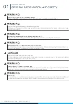
Page 15: ...ers including for third parties If possible use both hands when you handle heavy objects Bring in another person to help you if necessary When handling aligning positioning heavy individual components protective gloves and safety shoes must be worn Danger of tripping in the entire area around the unit Be aware of possible tripping hazards from cables lines installed on the floor Lines and cables m...

Page 16: ...damaged parts components wear protective gloves Dispose of damaged parts components properly and in an environmentally compatible way Observe country specific laws Danger of burns on the inside of the display case Do not touch any hot surfaces or products with bare hands Use suitable aids such as tongs to remove the products Let the display case cool down completely before any cleaning and mainten...

Page 17: ...isplay case cool down completely before any cleaning and maintenance work Danger of burns on the collecting tray or water bath Switch the unit off and let it cool down for at least 45 minutes before starting any cleaning work Crushing danger in the area of the base plate exclusively for units with heating climate Check the gas dampers of the base plate regularly to ensure they work and replace the...

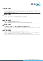
Page 18: ...on dismantling and maintenance work Wear safety shoes during installation and loading work Wear protective gloves during installation and loading work Wear eye protection when disposing of damaged parts components Wear a hard hat during installation lifting and loading work When cleaning the unit wear the respective protective equipment stipulated by the manufacturer of the cleaning agent being us...

Page 19: ...ting and unpacking the units When removing the wood cladding be aware of possible dangers from wooden parts that might fold back Bring in another person to help you if necessary The unit must be lifted with suitable load lifting equipment e g a forklift At least four persons must be employed to manually lift the unit These persons must be sufficiently strong Wear protective gloves and safety shoes...

Page 20: ...tective gloves Dispose of damaged parts components properly and in an environment friendly way Observe country specific laws WARNING Please note that some of the components of the unit are electronic parts Therefore it is not possible to dispose of them using public waste disposal companies Check your obligations in accordance with the national WEEE provisions It is mandatory to sort waste before ...

Page 21: ...21 NOTES CALEO HOT NEUTRAL ...

Page 22: ...pictures shown are for illustration purposes and do not necessarily correspond to the actual size or shape of your display case model Display case with dry heat No Name 1 Cover 2 Shelf no 1 black glass hotplate LED lighting supporting heat 3 Price tag holder 4 Side glass 5 Shelf no 2 black glass hotplate LED lighting supporting heat 6 Base shelf hotplate 7 Base Controller display Adjustable feet T...

Page 23: ...rotection glass 4 Side glass 5 Shelf no 2 black glass hotplate LED lighting supporting heat 6 Base shelf hotplate fold up 7 Maintenance flap heating elements angle sensor 8 Base including Controller display Transport rollers Water tank Filter Pump Revisionsklappe 1 2 3 4 5 7 8 6 Product basket large small with holder Chutes Glass shelf front side Cough and spit guard Bumpers in wood effect ...

Page 24: ... 1 Supporting heat 2 Lighting LED 3 Cough protection glass 4 Shelf no 1 black glass hotplate LED lighting supporting heat 5 Shelf no 2 black glass hotplate LED lighting supporting heat 6 Base shelf hotplate fold up 7 Float switch 8 Water bath 9 Heating element 10 Gas damper 11 Bottom tray with stopcock 1 2 3 4 5 6 7 8 9 10 11 ...

Page 25: ...erials Stainless steel 1 4301 1 4016 1 4404 Supplier components Primary heat Supporting heat LED Glass Electric cables and assembly materials cables cable ties etc Control box PCB display etc Glass Tempered safety glass 6 mm 8 mm Insulating glass 16 mm EN12150 2 2004 Due to the use of high quality and long lasting materials and supplier components a long service life can be expected with regular c...

Page 26: ...gs start to fade or become damaged over the course of the unit s service life they must be replaced by new signs without delay Their legibility and completeness must be checked at regular intervals Pictograms Descriptions Warning electrical hazard Warning electrical hazard Warning thermal hazard Protection class Earthing WARNING Hot surfaces inside Be careful when handling products Keep combustibl...

Page 27: ... be ensured Any deficiencies in the power supply must be resolved before connecting the unit The manufacturer of the unit is not responsible for damage caused by improper connection The following electrical connections must be ensured by the operator Units with 230V 50 60 Hz single phase 1x 16A Units with 400 V 50 60 Hz three phase 3x 16 A For units with 400 V electric connection a three pole main...

Page 28: ...have this damage confirmed 2 4 1 First steps To enable damage that is caused during loading transport and unloading to be traced all units are equipped with a so called Shockwatch 2 This tool makes it possible to determine the point of the delivery chain at which the product was damaged in order to clarify transport damage Information on the ShockWatch concept is stored in the QR code see Chapter ...

Page 29: ... on our web site The restraining and fastening elements enable installation on the floor or wall depending on the model Screw the restraining and fastening elements together with the corresponding installation materials depending on the condition of the floor wall Setting up Correct installation and trouble free operation are a prerequisite for putting the unit into operation The installation must...

Page 30: ... back to back or side by side To install the back wall connector proceed as follows Step 1 Check that the units are parallel to each other at the boundaries of the units Step 2 Attach the back wall connector tabs to both units as shown 3 holes each Step 3 Slide the connector into the back wall connector tab Do the same on both sides Ensure that the exhaust air duct is not covered or dirtied Air ci...

Page 31: ...ccessible to be able to disconnect the unit from the power grid if need be cleaning maintenance work If direct wiring is used a means of disconnecting the unit from the power grid must be created The unit must be leveled after assembling NOTE Connecting the units in the base All the units must be connected in the base A blind rivet nut is pre installed in the base on each side of the unit for this...

Page 32: ...at the stopcock of the drain hose is closed during operation if no drain has been provided by the customer depending on the model When using a customer provided drain the drain hose can be connected directly to it The drain must be equipped with a siphon This prevents cold air and odours from penetrating the display case ...

Page 33: ...3 Malfunction of primary secondary heat unit defective Contact a service technician Lighting does not work LED lighting not switched on Switch on lighting see Chapter 3 Primary and or secondary heat does not become hot cannot be regulated Unit is not switched on Switch unit on Controller or fuse defective Contact a service technician Heat radiator and or bot tom tray heating tray do not become hot...

Page 34: ... in the supporting heat sensor or the sen sor is defective Contact a service technician Error message on the display F2H F1L Fault in the primary hotplate or the sensor is defective Contact a service technician Error message on the display F3H F3L Fault in the angle sensor of the water bath Contact a service technician Error message on the display F10 Fault in the float or water bath Water bath or...

Page 35: ...35 NOTES CALEO HOT NEUTRAL ...

Page 36: ...up check the cable connections and power supply for correctness and contact DANGER The unit is pre cleaned before delivery Nevertheless we still recommend that you clean the unit thoroughly with a suitable cleaning agent see Chapter 3 5 2 Before stocking the unit with products wait until the desired temperature is reached NOTE After a power cut the unit starts in the last operating mode NOTE ...

Page 37: ... power supply NOTE Button Description Function 1 CONTROLLER DISPLAY Displays settings changes values faults 2 SUPPORTING HEAT Supporting heat ON OFF 3 heating levels 3 PRIMARY HEAT See unit with climate controlled heat 4 5 LED LIGHTING Light ON OFF 6 PROGRAMS Saveable programs P1 to P7 7 ON OFF Heated display case ON OFF 8 DISPLAY P1 TO P7 Program display red active 2 3 4 5 6 7 8 1 ...

Page 38: ...ff press button 6 By pressing the buttons the supporting heat 1 and primary heat 3 can be activated separately from each other with three levels each The heating levels are shown visually on the controller display After the unit has been switched on the controller display 1 always shows power level NEUTRAL for all heat sources The unit does not heat up The light can be switched on and off 1 The li...

Page 39: ...LAY Displays settings changes values faults 2 SUPPORTING HEAT Supporting heat ON OFF 3 heating levels 3 PRIMARY HEAT Primary heat ON OFF 3 heating levels 4 HUMIDIFICATION Humidification ON OFF 3 in tensity levels 5 LED LIGHTING Light ON OFF 6 PROGRAMS Saveable programs P1 to P7 7 ON OFF Heated display case ON OFF 8 DISPLAY P1 TO P7 Display red active ...

Page 40: ...porting heat 2 primary heat 3 and humidification 4 can be activated separately in 3 levels each The heating levels are shown visually on the controller display When the unit has been connected to the power supply OFF appears on the display To switch on and off press button 7 Switch the light on off 5 by pressing button The unit offers the option of neutral operation unheated all heating levels are...

Page 41: ...NG Set the temperature to match your product Too high a temperature leads to the product drying out or burning Observe the maximum carrying capacity of the large small product basket Observe the maximum carrying capacity of the large small product basket Maximum load Small product basket total 5 kg Large product basket total 15 kg When stocking the unit a minimum distance of 80 mm must be kept fro...

Page 42: ...power mains DANGER Danger of being struck by the unit during installation cleaning and maintenance work Be aware of possible dangers of being struck by the unit WARNING 3 4 1 Information on cleaning and testing Switch the unit off before any cleaning work We recommend performing the daily cleaning at the end of the working day The unit can remain switched off overnight or outside of business hours...

Page 43: ...ng points are important Always keep the stainless steel surfaces clean Ensure adequate air circulation on the surfaces Never touch components of the unit with rusty or sharp material Components Black glass plates shelves depending on the model x Heat bridge x Lighting x Controller display x Collecting tray bottom tray wastewater tap x Water mains connections and hose connections depending on the m...

Page 44: ...r rough cleaning utensils LED Soft cloth Only clean dry Hook in frames with containers dividing bars base decks Washing up liquid brush Base decks and containers are easy to remove see Chapter 2 1 Only use brushes with plastic or natural bristles Only the cleaning agents mentioned above are permissible for cleaning the unit Never use the following cleaning agents Do not use any strong smelling cau...

Page 45: ...it cool down for at least 45 minutes before starting any cleaning work WARNING Remove the steam baffle on the back wall upwards NOTE Be aware of possible sharp edges when disassembling the steam baffles Use protective gloves NOTE Lift the steam baffles over the recesses hole from the rear wall and clean them according to the specifications in Chapter 3 5 3 ...

Page 46: ... the provided grips Carefully remove the float ensuring that you do not twist it in the process the holders may break Only clean the water bath after removal of the float The float must be cleaned exclusively by hand We recommend using a scale removing cleaning agent that is suitable for stainless steel Rinse all parts with clear water to prevent any residues When reinserting the float in the hold...

Page 47: ...rior of the bottom tray can be cleaned Connect the drain hose of the bottom tray to a drain or place a suitable collecting container under it Open the ball valve and start cleaning After the bottom tray has been cleaned and rinsed with clear water close the ball valve and store the drain hose back in the base No Designation 1 Ball valve 2 Water filter 3 Water tank 1 2 3 The container for cleaning ...

Page 48: ...ed out of the water tank when the minimum water level is reached The water tank has a capacity of 15 litres and must be filled with fresh water daily before starting the unit Each unit has a monitoring system which triggers an acoustic warning signal and switches off the steam production if the water level in the tank falls below the set level water tank is empty An error message fault H2O appears...

Page 49: ...ow cap Every time after inserting the filled water tank press buttons 2 and 4 simultaneously for 7 seconds to acknowledge the message and restart the humidity supply see Chapter 3 2 2 If no water is added within 30 minutes of the warning signal being sounded the water tray heater switches off automati cally The product still stays up to temperature by means of the primary and supporting heat NOTE ...

Page 50: ...water filter and turn it clockwise until it is hand tight 4 Turn the water supply back on 5 Press the buttons 2 and 4 simultaneously for 5 seconds while the unit is turned off to acknowledge the message on the display see Chapter 3 2 2 6 After replacing the filter check the filter head for leaks when the unit is started up forthe first time Irrespective of the remaining capacity the filter must be...

Page 51: ...onal check Daily Weekly Monthly Black glass plates shelves depending on the model x Heat bridge x Lighting x Mechanical damage on all components listed in Chapter 2 1 x Controller display x Collecting tray bottom tray wastewater tap x Water and hose connections depending on the model x Gas damper depending on the model x Steering and fixed position casters depending on the model x Interval ...

Page 52: ...ALEO HOT NEUTRAL 03 3 4 10 Checking the gas damper Danger from defective gas damper Check the gas damper of the primary hotplate monthly to ensure it is functioning properly Replace it if it is defective Observe the service life and maintenance intervals indicated by the manufacturer DANGER ...

Page 53: ...is die Wartung Kontrolle und Reparatur abgeschlossen ist Ein un beabsichtigtes Einschalten muss verhindert werden DANGER The unit must be switched off by the main switch until the maintenance inspection and repair work is completed Switching on inadvertently must be prevented Technical changes to the unit may only be carried out by authorised specialists This applies in particular to work on the e...

Page 54: ...contact your supplier or specialist dealer Each unit is equipped with a rating plate see Chapter 1 7 Please inform the authorised specialist of the unit data shown here The information on the type and serial number and the date of construction are required for allocating the unit Spare parts lists for your unit can be found in the Downloads menu at www ideal ake at ...

Page 55: ...liances Safety Part 1 General Requirements EN 60335 1 2012 AC 2014 A11 2014 A13 2017 A1 2019 A2 2019 A14 2019 IEC 60335 1 2010 modified A1 2013 modified A1 2013 COR1 2014 A2 2016 A2 2016 COR1 2016 EN 60335 2 49 2003 Household and similar electrical appliances Safety Part 2 49 Particular requirements for commercial electric appliances for keeping food and crockery warm EN 60335 2 49 2003 AC 2007 EN...

Page 56: ...56 NOTES CALEO HOT NEUTRAL ...

Reviews: