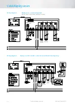
Cold display cases
Technical changes reserved
Valid from October 2014
70
Description of functions
R
USER LEVEL
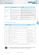
Control circuit 1: Hysteresis
In this parameter, you can specify the control hysteresis.
A small hysteresis enables exact control, but will result in frequent switching of the relay.
Defrosting interval
The defrosting interval defines the time after which a defrosting operation is started. Once the defrosting
operation is triggered, the defrosting interval starts again. A defrosting operation can also be triggered by
pressing the
UP
button („manual defrosting“) for at least 3 seconds or another parameterised button. Via the
internal week timer, defrosting can also be started in real time. Once switched on, the controller starts
refrigeration immediately and will trigger the first defrosting operation as soon as the time set in
has elapsed. If
[
=0], no automatic defrosting operation will be performed.
Defrosting mode
In this parameter, you can define if defrosting is to be performed and, if yes, how it is to be performed.
You can choose among simple shut-down of the compressor, defrosting by electric heating or by hot gas.
Electric defrosting will always be performed after a compressor break, defined in
.
Hot gas defrosting will
always be performed directly after a refrigeration phase. Additionally, you can define via parameters
and
if
the cold store temperature is to be lowered before defrosting.
Defrosting temperature
A defrosting operation is complete as soon as the temperature set here is reached at the evaporator.
If the defrosting operation is not completed within the time set in
, it will be stopped.
Fan speed in control mode, Set1
Fan speed in normal control mode and active Set1
Fan speed during defrosting, Set1
Fan speed during defrosting and active Set1
Calibration of sensor F1 actual value correction
With this parameter it is possible to correct actual value deviations caused by sensor tolerances, very long sensor
cables or structural protections (e.g. ex-barriers), for example. The value defined here is added to the measured
value.
Actual value sensor F1
The temperature value shown here is used for control. It is calculated as follows:
Actual control value = ( actual measured value * weighting factor ) + actual value correction
Actual value correction and weighting factor must be defined in the following parameters. This corrects actual
value deviations in special applications (refrigerated shelves or similar) due to unfavourable sensor location.
Display in standby mode
In this parameter, you can define what is to be displayed in standby.
J
Pre-defined parameter sets
J
Internal: active data set
With this parameter, you can set up pre-defined data sets. The data sets are provided by Störk-Tronic. If a new data
set is loaded, all previously set parameters will be overwritten. After that, they can be edited as required.
Summary of Contents for Gastro O-53
Page 37: ...Pers nliche Notizen Personal notes...
Page 38: ......
Page 39: ...User manual COLD DISPLAY CASES self contained or remote refrigerated...
Page 75: ...Personal notes...


