Supplied By www.heating spares.co Tel. 0161 620 6677
12
British Gas RD1
-
Installation & Servicing
INSTALLATION
8
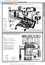
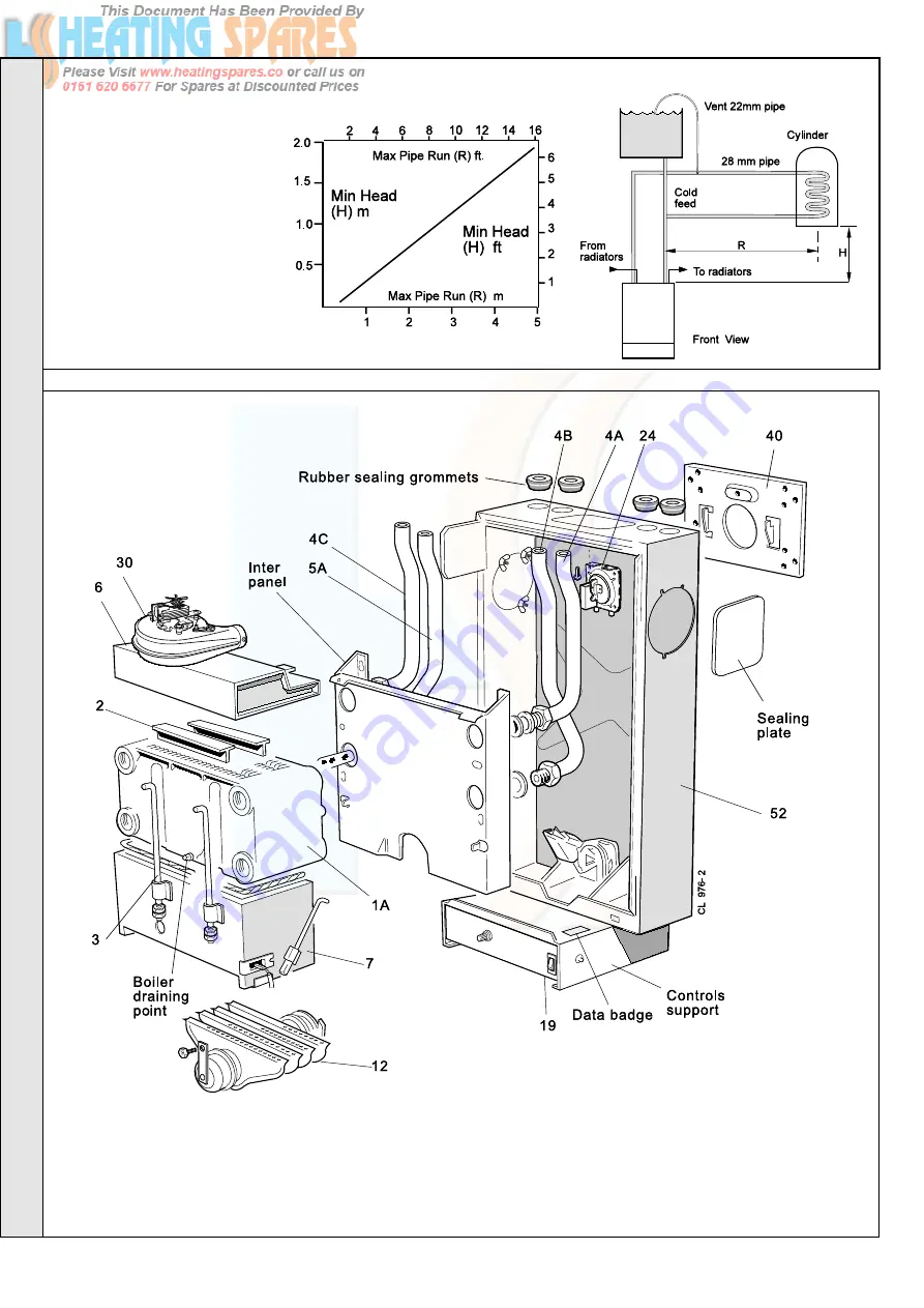
BOILER ASSEMBLY - Exploded view
30 shown
LEGEND
1A.
Heat exchanger.
2.
Flue baffles.
3.
Tie rods.
4A.
Pumped flow pipe.
4B.
Gravity return pipe.
4C.
Gravity flow pipe.
5A.
Pumped return pipe.
6.
Collector hood assembly.
7.
Combustion chamber.
12.
Main burner.
19.
Control box .
24.
Pressure switch.
30.
Fan.
Note.
Gravity horizontal pipes should be ABOVE ceiling level and as SHORT
as possible. A MINIMUM inclination
of 25mm per 3m run (1" per 10') is
required to avoid air locks. If these
conditions cannot be met, pumped
primaries MUST be used.
The 100 is not suitable for gravity
circulation.
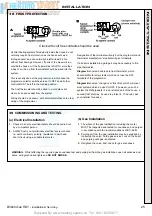
The graph assumes 8 elbows in the
gravity circuit. For each elbow in
excess of 8, (R) must be reduced by
300 mm (12 in.) or (H) increased by
100 mm (4 in.)
7
REQUIREMENTS FOR CORRECT GRAVITY HOT WATER PERFORMANCE
40.
Wall mounting plate.
52.
Back panel.
INST
ALLA
TION


