Supplied By www.heating spares.co Tel. 0161 620 6677
British Gas RD1
-
Installation & Servicing
23
INSTALLATION
Cla
1794
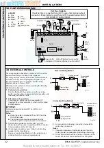
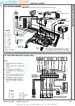
MAINS
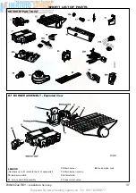
Fan
Flue sensor
Flow sensor
Return sensor
Air pressure switch
Detection probe
Hot surface igniter
Gas valve
Read
Note 1
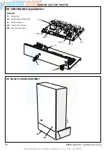
Earth stud,
Controls support
Boiler control
potentiometer
Earth stud
Control box
(RHS)
Reset
switch
Overheat
thermostat
Note 1. If switched live is connected here (EC1) leave other
terminal without connection. If programmer is used here
(EC1) the switched live MUST BE FUSED AT 2A MAXIMUM.
y/g
br b
LN
CH1
or
or
r
bk
PL
PN
EC1
EC2
gy
w
w w
w
w
CH2
b
b
r
r
br
b
pky
w
w
gy w oror
r
b
b
r
r
w
w
b
br
y y
y/g
y/g
y/g
y/g
pky w
pk
y
r r
r
w
34 PICTORIAL WIRING
LEGEND
b
blue
bk
black
br
brown
r
red
y
yellow
w
white
or
orange
v
violet
pk
pink
gy
grey
y/g
green/yellow
IMPORTANT.
No system controls to be wired in this mains supply.
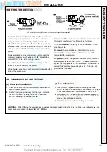
Notes.
1.
Some earth wires are omitted for
clarity.
Ensure proper earth continuity when
wiring.
2.
For numbering of terminals on
thermostats see the manufacturer's
literature.
3.
This is a fully controlled system - set
the boiler thermostat to maximum.
4.
Switchmaster (Smiths) valves are
similar but the wiring is different.
Consult the diagram supplied with
valve.
LEGEND
b
blue
bk
black
br
brown
r
red
w
white
y/g
yellow/green
or
orange
gy
grey
35 MID POSITION VALVE (Pumped only)
INST
ALLA
TION


