23
British Gas 440 - 480 RD2 -
Installation & Servicing
INSTALLATION
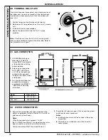
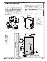
33 ELECTRICAL CONNECTIONS
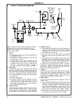
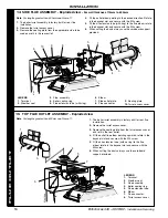
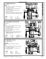
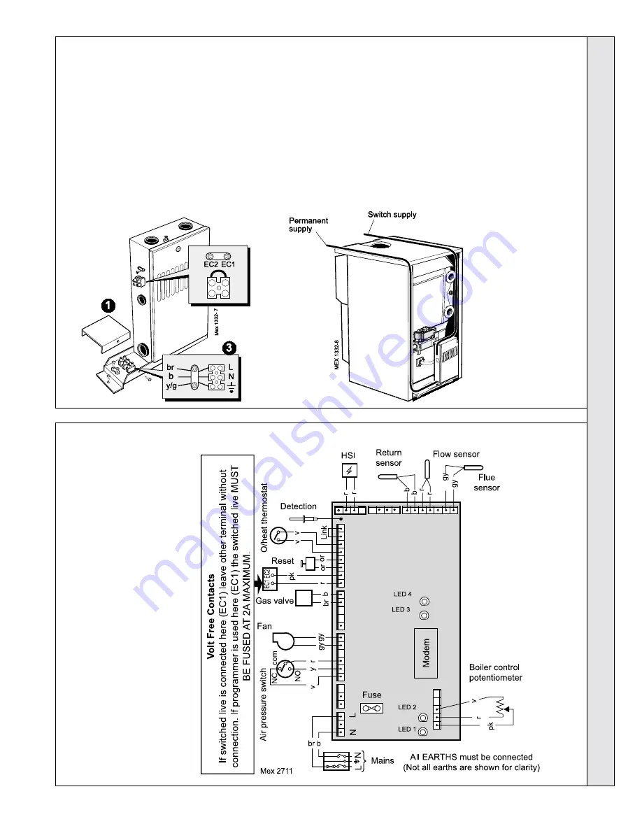
34 FLOW WIRING DIAGRAM
WARNING. The appliance must be efficiently earthed.
A mains supply of 230 V ~ 50 Hz is required.
All external controls and wiring must be suitable for mains
voltage. Wiring should be in 3-core PVC insulated &
sheathed cable, not less than 0.75mm
2
(24 x 0.2mm) to BS.
6500 Table 16 Wiring Regulations and local regulations.
Connection must be made in a way that allows complete
isolation of the electrical supply - such as a double pole
switch, having a 3mm (1/8") contact separation in both poles
or a plug and socket serving only the boiler and system
controls. The means of isolation must be accessible to the
user after installation.
Notes.
1. If a programmer is
fitted refer to the
instructions
provided and
Frame 35.
2. For gravity DHW
applications the
pump MUST be
wired through the
programmer.
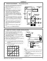
1. Remove the securing screw and lift off the mains terminal
box cover.
2. Route the mains cable from the LH rear of the boiler, along
the front of the baseplate to the terminal box.
Note.
Leave sufficient length of cable to enable it to be routed
as shown once the casing has been refitted and secure to
the casing with the ties provided.
3. Connect the live, earth and neutral wires into the terminal
strip.
4. Secure the mains lead with the cable clamp.
5. Refit the terminal box cover.
IMPORTANT.
Control switching must not take place in this mains supply.
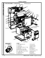
LEGEND
b
blue
bk black
br brown
gy grey
or orange
p
pink
r
red
v
violet
w white
y/g yellow/green
INST
ALLA
TION

