Classic
LXRS, RS
-
Propane Installation
15
INSTALLATION
24 COMMISSIONING AND TESTING
A.
ELECTRICAL INSTALLATION
1.
Checks to ensure electrical safety should be carried out by
a competent person.
2.
ALWAYS carry out preliminary electrical system checks, i.e.
earth continuity, polarity, resistance to earth and short
circuit using a suitable test meter.
3.
Refit the control box.
INST
ALLA
TION
WARNING
.
Whilst effecting the required gas soundness test and purging air from the gas installation,
open all windows and doors, extinguish naked lights and
DO NOT SMOKE.
repeatedly until the pilot is seen to light through the
sightglass (B).
6.
Hold the gas control knob depressed for 15 seconds after
the pilot burner has ignited, then release.
7.
If the pilot burner fails to remain alight at this stage, repeat
the procedure detailed above but wait longer than 15
seconds before releasing the gas control knob.
8.
Check the appearance of the pilot flame to ensure that it
envelopes the tip of the thermocouple and is
approximately 25mm (1") long.
The pilot flame is factory set and no adjustment is possible.
If the pilot flame is incorrect refer to Frame 35 .
9.
Check that the electricity supply and all external controls
are ON.
10.
Set the boiler thermostat control knob to position 6 and
check that the burner cross-lights smoothly from the pilot
flame.
11.
Test for gas soundness around the boiler gas component
joints, using leak detection fluid.
12.
Operate the boiler for 10 minutes to stabilise the burner
temperature.
13.
The boiler is pre-set at the factory to its nominal rating.
Check the burner pressure against the values quoted in
Table 2, page 3. The inlet pressure measured at the gas
control valve must be 37mb.
14
. Set the boiler thermostat control knob to OFF. Remove the
pressure gauge tube and tighten the sealing screw in the
pressure test point. Relight and check for gas soundness
at the pressure test point.
15. Deluxe Model (LX)
- Refit the controls casing bottom panel
and screws.
Standard Model
- Refit the controls pod and tighten the
front fixing screws.
16. Deluxe Model (LX)
- Lower the glass fascia to its closed
position.
Standard Model
- Close the pod door.
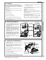
1.
Check that all drain cocks are CLOSED and any valves
in the flow and return lines are OPEN.
2.
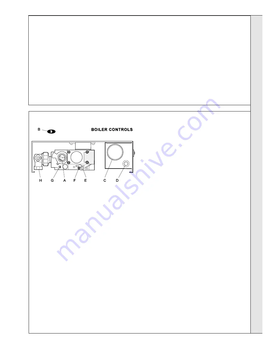
Check that the gas service cock (H) is OPEN and that the
boiler thermostat control knob (C) is OFF.
Deluxe Model (LX)
- Fit the boiler casing (Frame 26) but
do not fit the controls casing bottom panel.
Standard Model
- Fit the boiler casing (Frame 26) but do
not fit the controls casing pod.
3.
Loosen the screw in the burner pressure test point (E)
and connect a gas pressure gauge via a flexible tube.
4.
Turn the gas control knob clockwise until resistance is felt
and then release.
WAIT FOR 3 MINUTES.
5.
Push in and retain fully depressed the gas control knob
(A). Press and release the piezo unit button (D)
E
Burner pressure test point
F
Main burner pressure adjuster
G
Inlet pressure test point
H
Gas service cock
LEGEND
A
Gas valve control knob
B
Sightglass
C
Thermostat control knob
D
Piezo unit ignition
25 INITIAL LIGHTING
B.
GAS INSTALLATION
1.
The whole of the gas installation MUST be inspected
and tested for soundness, and purged in accordance
with the recommendations of BS. 6891.
2.
Purging air from the gas installation may be expedited by
loosening the union on the gas service cock on the
boiler and purging until gas is detected.
3.
Retighten the union and check for gas soundness.


