28
Henrad SE FF
- Installation
INSTALLATION
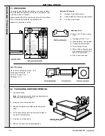
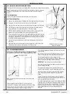
43 BOILER WATER CONNECTIONS
The boiler flow and return pipes are supplied fitted to the boiler and ready for top connection.
INST
ALLA
TION
Note.
For boiler sizes SE 30 FF to SE 60 FF use the 28mm x 22mm connectors
supplied in the hardware pack, to reduce the boiler flow and return pipes to
22mm.
TOP CONNECTION
Connect the system pipework to the boiler flow and return pipes.
BOTTOM CONNECTION
1. Remove the retaining pin and withdraw the thermostat phial from the pocket.
2. Disconnect the electrical leads from the overheat thermostat.
3. Undo the flow and return pipe unions and withdraw the pipes from the boiler.
4. Cut off the spun ends of the pipes and connect pipes of suitable length to
terminate 50mm (2") outside the bottom of the boiler casing.
5. Refit the pipe assemblies to the flow and return bosses, ensuring that the
gaskets are in position. Note.
Fit the return pipe assembly first.
6. Fit an
automatic air vent to the top of the return pipe assembly and a manual
air vent to the top of the flow pipe assembly (where pressures may at times
be negative). Alternatively, a combined feed and vent pipe may be connected
to the top of the flow pipe assembly.
7. Connect the system pipework to the flow and return pipes at the bottom of
the boiler.
8. Reconnect the overheat thermostat electrical leads and re-insert the boiler
thermostat phial into the pocket, retaining it with the split pin.
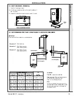
(Pipework shown as a dotted
line is not supplied)
3
4
6
1
2
Centre line of boiler
145 mm
Condensate
drain
42 mm
Note.
The drain connection is located at the rear of the controls
compartment.
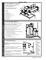
The condensate drain provided on the boiler must be
connected to a drainage point, preferably within the building.
Ensure that the condensate siphon is full of water before
commissioning the boiler. Refer to Frame 20 or 28.
Refer also to the British Gas document: 'Guidance Notes for
the Installation of Domestic Gas Condensing Boilers' (1989)
44 CONDENSATE DRAIN
A 'tun dish' arrangement between the boiler and the drain
may be fitted.
The routing of the drain must be made to allow a minimum
fall of 1 in 20 away from the boiler, throughout its length.
The drainage pipework must be arranged so that
obstruction (e.g. through freezing) of external drainage pipe
does not give rise to spillage within the dwelling.
IMPORTANT. Any external runs must be insulated.
Excessive external pipe runs should be avoided in order to
prevent possible freezing.
All pipework and fittings in the condensate drain system
must be made of plastic. No other materials may be used.
The drain outlet on the boiler is standard 22mm overflow
pipe. This size must not be reduced in any part of its
length.
In order to defer the onset of freezing of the condensate
drain when the pipe is run externally the pipe should be run
as far as possible within the building.
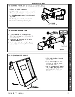
The boiler condensate drain connection is suitable for Bartol
'Polypipe' tubing. An adaptor is supplied to allow the use of
Marley 'Terrain' tubing, which is slightly larger. This adaptor
should be sealed to the Marley 'Terrain' tubing and to the
boiler condensate drain, using a suitable plastic tube
adhesive.
Summary of Contents for Henrad SE 30 FF
Page 1: ......

