background image

50

Henrad SE FF 

- Installation

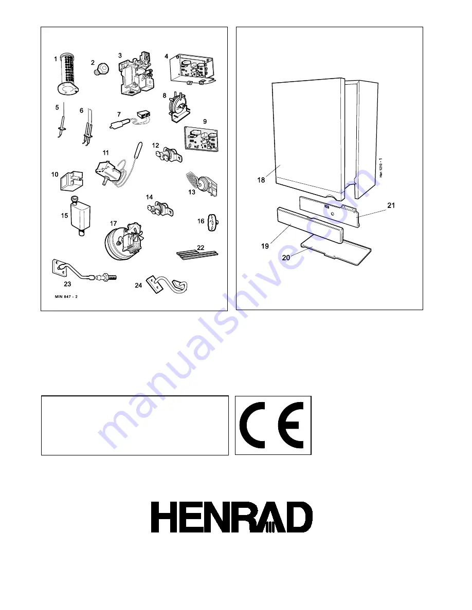
86 BOILER CASING ASSEMBLY

85 SHORT PARTS

SHORT LIST OF PARTS

Henrad Installer/Technical Helpline Tel: 01482 498663

Caradon Plumbing Limited
pursues a policy of continuing
improvement in the design and
performance of its products. The
right is therefore reserved to vary
specification without notice.

December  1999 UIN 153 960 A02

Technical Training

Caradon Plumbing Limited, P.O. Box 103, National Ave, Kingston upon Hull, HU5 4JN. Telephone:  01482
492 251 Fax: 01482 448 858. Registration No. London 322 137. Registered Office: National Avenue,
Kingston upon Hull, HU5 4JN. 

A subsidiary of Caradon p.l.c

The Caradon Plumbing Limited Training Centre offers a
series of first class training courses for domestic,
commercial and industrial heating installers, engineers
and system specifiers.  For details of courses please ring:

...................................................................... 01270 413 624

Summary of Contents for Henrad SE 30 FF

Page 1: ......

Page 2: ...2 Henrad SE FF Installation ...

Page 3: ...y SEDBUK 86 1 86 7 86 4 86 3 86 5 86 3 Boiler Size SE 30 FF SE 40 FF SE 50 FF SE 60 FF SE 70 FF SE 80 FF Gas supply connection in BSP Rc 1 2 1 2 BSP Female Flow connection 22mm copper via adaptors 28mm copper FEMALE supplied MALE Return connection 22mm copper via adaptors 28mm copper FEMALE supplied MALE Maximum static water head m ft 30 5 100 Minimum static water head m ft 0 45 1 5 Electrical sup...

Page 4: ...st of Parts 48 System Diagrams 9 Terminal Guards 7 Thermostatic Radiator valves 8 Water and Systems 8 Water Connections 5 Water Treatment 12 Wiring Diagrams 24 SE FF Natural Gas only SE 30 FF G C Appliance No 41 387 46 SE 40 FF G C Appliance No 41 387 47 SE 50 FF G C Appliance No 41 387 48 SE 60 FF G C Appliance No 41 387 49 SE 70 FF G C Appliance No 41 387 50 SE 80 FF G C Appliance No 41 387 51 D...

Page 5: ...he hardware pack b This appliance is NOT suitable for use with a direct hot water cylinder 1 BOILER WATER CONNECTIONS 2 BOILER CLEARANCES all dimensions in mm in The following minimum clearances must be maintained for operation and servicing Additional space will be required for installation depending upon site conditions Side and Rear Flue a Provided that the flue hole is cut accurately e g with ...

Page 6: ... in a timber framed building it should be fitted in accordance with the Institute of Gas Engineering document IGE UP 7 1998 INTRODUCTION SE 30 80 FF are fully automatically controlled wall mounted low water content balanced flue fanned super efficient condensing gas boilers They are spot rated to provide central heating outputs of 8 8 kW 30 000 Btu h to 23 4 kW 80 000 Btu h Due to the high efficie...

Page 7: ... code FLUE INSTALLATION Pluming will occur at the termination so where possible terminal positions which could cause a nuisance should be avoided The flue must be installed in accordance with the recommendations of BS 5440 Part 1 The following notes are intended for general guidance GENERAL 1 The boiler MUST be installed so that the terminal is exposed to external air 2 It is important that the po...

Page 8: ...rature differential is shown in Table 4 Boiler size SE30FF SE40FF SE50FF SE60FF SE70FF SE80FF Boiler kW 8 8 11 7 14 7 17 6 20 5 23 4 Output Btu h 30 000 40 000 50 000 60 000 70 000 80 000 Water Flow l sec 0 19 0 25 0 32 0 38 0 44 0 51 Rate gpm 2 5 3 3 4 2 5 0 5 8 6 7 Pressure kPa 4 2 6 7 10 0 13 7 11 2 13 7 Loss m 0 4 0 7 1 0 1 4 1 2 1 4 ft 1 4 2 3 3 3 4 6 3 8 4 6 THERMOSTATIC RADIATOR VALVES TRV ...

Page 9: ... achieved using a room thermostat whilst other rooms are individually controlled by thermostatic radiator valves 2 Open all manual or thermostatic radiator valves and adjust the lockshield valves on remaining radiators to give around 11 C temperature drop at each radiator 3 Turn up the cylinder thermostat and adjust the cylinder balancing valve so that the cylinder achieves a maximum flow consiste...

Page 10: ...ding into the feed expansion cistern to a minimum a A non adjustable preset lift pressure not exceeding 3bar 45lb in2 b A manual testing device c Provision for connection of a discharge pipe The valve or discharge pipe should be positioned so that the discharge of water or steam cannot create a hazard to the occupants of the premises or cause damage to electrical components and wiring 3 Pressure G...

Page 11: ...le still hot Refill and vent the system Adjust the initial pressure to the required value 4 Expansion Vessel a A diaphragm type expansion vessel must be connected to a point close to the inlet side of the pump the connecting pipe being not less than 15 mm 1 2 nominal size and not incorporating valves of any sort b The vessel capacity must be adequate to accept the expansion of the system water whe...

Page 12: ...NIUM alloy heat exchanger If water treatment is used Caradon Plumbing Limited recommend only the use of FERNOX COPAL or SENTINEL X100 water treatment products which must be used in accordance with the manufacturers instructions For further information contact Sentinel Division Betz Dearborn Ltd Widnes Cheshire WA8 8UD 0151 424 5351 Fernox Manufacturing Co Ltd Tandem House Marlowe Way Croydon Surre...

Page 13: ...e siphon 16 Thermostat knob 17 Fan assembly 18 Front panel 19 Controls door 20 Bottom panel 23 Low pressure sensing pipe LEGEND A Boiler drain point 1 Main burner 3 Gas valve 4 Control box 8 Pressure switch 10 Spark generator 10 BOILER ASSEMBLY Exploded view 24 Fan pressure sensing pipe 25 Heat exchanger 26 Flow pipe 27 Return pipe 36 Wall mounting plate ...

Page 14: ...rn pipe connectors SE 30 FF to SE 60 FF boilers ONLY M5 x 10 pozi Hex screw Hardware Pack Boiler Pack Contents Hardware Pack listed below These Installation Servicing Instructions The User s Instructions 1 Unpack the boiler Note The hardware pack and wall mounting plate are within the cardboard infill pieces 2 Swing open the controls pod door 3 Remove the single screw retaining the casing front pa...

Page 15: ...r spacing LHS 1 Undo the 3 retaining screws 2 Push the panel backward then to the right to withdraw it from the boiler 3 Unpack the boiler flue kit and extension packs if used 14 DETERMINING THE FLUE LENGTH AND FLUE PACKS REQUIRED Flue length dimension Flue Rear flue Right hand side Left hand side packs dimn X flue dimn Y flue dimn Z required 114 580 mm 114 460 mm 114 550 mm Pack B2 cut down 4 1 2...

Page 16: ...ut the flue hole preferably with a 5 core boring tool ensuring that the hole is square to the wall Both wall faces immediately around the cut hole should be flat 2 Drill 3 holes with a 7mm 1 4 masonry drill and insert the plastic plugs provided for the wall mounting plate and the jacking screw plate 3 Locate two No 10 x 2 screws in the wall mounting plate one at each side in any of the 3 holes pro...

Page 17: ...cardboard support cutting aid 20 MOUNTING THE BOILER 1 Fit the cut to length flue on to the flue turret Note Ensure the top groove in the flue aligns with the top of the turret 2 Drill a 3 2mm dia hole through the flue via the hole present in the turret 3 Secure the turret to the flue using the self tapping screw provided 1 Lift the boiler onto the wall mounting plate as shown 2 Check the boiler a...

Page 18: ...e ground level an approved terminal guard should be fitted Refer to Flue Installation Page 7 REAR FLUE OUT LET Note BEFORE fitting the flue turret fill the condensate siphon within the boiler by pouring a cupful of water into the flue outlet A 1 Insert the flue assembly through the prepared hole in the wall far enough to allow the rubber seal to unfold completely and form an adequate seal on the o...

Page 19: ...ng a The two wall mounting plate screw positions choose one from each group and the jacking screw position b The position of the flue duct hole see diagram below and template Note Mark the centre of the hole as well as the circumference 5 Remove both templates from the wall 23 FLUE ASSEMBLY Exploded view SIDE FLUE OUTLET 2 When cutting the ducts always use the cardboard support cutting aid provide...

Page 20: ...cause damage or personal injury 1 Cut the flue hole preferably with a 5 core boring tool ensuring that the hole is square to the wall Both wall faces immediately around the cut hole should be flat 2 Drill 3 holes with a 7mm 1 4 masonry drill and insert the plastic plugs provided for the wall mounting plate and the jacking screw plate Note If the terminal is to be sited within 25 40mm of a corner o...

Page 21: ... of water into the flue outlet A 1 Insert the flue assembly through the prepared hole in the wall far enough to allow the rubber seal to unfold completely and form an adequate seal on the outside wall 2 Pull the flue back and locate the flue turret on the top of the boiler ensuring that the seal is in place 3 Secure the flue turret on top of the boiler by inserting the open ends of the turret clam...

Page 22: ...ave been accurately cut and the outside wall face is flat 1 Position the terminal wall plate over the terminal 2 Drill 4 fixing holes with a 7mm 1 4 masonry drill 3 Insert the 4 plastic plugs provided 4 Secure the plate with 4 of the No 10 x 2 screws provided Note If the terminal is less than 2m 6 6 above ground level an approved terminal guard should be fitted Refer to the Flue Installation Page ...

Page 23: ...ING THE KIT INSTALLATION INSTALLATION 34 ELECTRICAL CONNECTIONS Appliances fitted with a REAR outlet flue please refer to Frame 19 Appliances fitted with a SIDE outlet flue please refer to Frame 27 WARNING This appliance MUST be efficiently earthed A mains supply of 230 V 50 Hz is required The fuse rating should be 3 A All external controls and wiring MUST be suitable for mains voltage Wiring shou...

Page 24: ...stems wiring diagram supplied by the relevant manufacturer in conjunction with the wiring diagrams shown in Frames 38 to 41 Difficulty in wiring should not arise providing the following directions are observed 1 Controls that switch the system on and off e g a time switch MUST be wired in series in the live mains lead to the boiler Flow wiring diagram LEGEND b blue bk black br brown r red o orange...

Page 25: ...ty when wiring 2 This is a fully controlled system set the boiler thermostat to MAXIMUM 3 Numbering of thermostat terminals applies only to the manufacturer mentioned w white g y green yellow gy grey or orange v violet pk pink LEGEND b blue bk black br brown r red y yellow INSTALLATION LEGEND b blue bk black br brown r red w white or orange y yellow g y green yellow ...

Page 26: ... the boiler thermostat to MAXIMUM 3 Numbering of thermostat terminals applies only to the manufacturer mentioned 4 The boiler should be sized for radiator load only 5 A clock stat may be used instead of separate room stat and time switch 1 Some earth wires are omitted for clarity ensure proper earth continuity when wiring 2 Numbering of thermostat terminals applies only to the manufacturer mention...

Page 27: ...e or if the boiler will be left off for more than a day or so then a frost thermostat should be wired into the system This is usually done at the timer in which case the timer selector switches are set to OFF and all other controls MUST be left in the running position The frost thermostat should be sited in a cold place but where it can sense heat from the system Wiring should be as shown with min...

Page 28: ...plied 3 4 6 1 2 Centre line of boiler 145 mm Condensate drain 42 mm Note The drain connection is located at the rear of the controls compartment The condensate drain provided on the boiler must be connected to a drainage point preferably within the building Ensure that the condensate siphon is full of water before commissioning the boiler Refer to Frame 20 or 28 Refer also to the British Gas docum...

Page 29: ...B to OFF 16 Switch the electricity supply OFF 17 Remove the pressure gauge and tube Replace the sealing screw in the pressure test point Ensure a gas tight seal is made 18 Refit the boiler front and bottom panels using the screws previously removed 19 Close the controls pod door LEGEND A Burner on neon B Thermostat knob C Gas service cock D Inlet pressure test point E Burner pressure test point F ...

Page 30: ...er s requirements Knob Setting Flow Temperature C F 1 50 120 2 60 140 3 66 150 4 71 160 5 77 170 6 82 180 After completing the installation and commissioning of the system the installer should hand over to the householder by the following actions 1 Hand the User s Instructions to the householder and explain his or her responsibilities under the Gas Safety Installation and Use Regulations 1994 amen...

Page 31: ...wish to undertake the service contract yourself or alternatively offer to the customer the benefits of the Henrad Care Scheme details of which are outlined in the Householder pack supplied with this boiler Note Some aluminium oxide build up on the heat exchanger fins is quite usual with this type of condensing boiler Though removal is recommended annually the heat exchanger MUST be inspected and c...

Page 32: ... ignition and detection leads are in good condition and renew as necessary 1 Disconnect the electrical leads from the fan 2 Disconnect the pressure sensing pipe from the fan a Undo the 2 screws securing the pipe to the fan b Undo the 2 screws securing the pipe clamping plate to the manifold block c Withdraw the clamping plate d Withdraw the pipe from the boiler 3 Press the retaining bracket lever ...

Page 33: ...service cock 9 Reconnect the electrical supply 55 CLEANING THE HEAT EXCHANGER 1 Place a plastic sheet or similar beneath the boiler and remove all visible loose deposits from the heat exchanger fins using a suitable brush 2 Take care to clean debris from the ledge inside the combustion chamber Note The pressure sensing pipes must be tested for gas soundness THEBOILERMUSTNOTBEOPERATEDIFTHESEALINGPA...

Page 34: ...nel need not be removed 2 Disconnect the overheat thermostat electrical leads 3 Undo the 2 securing screws and withdraw the thermostat 4 Fit the new overheat thermostat and reassemble in reverse order Refer also to Frame 10 Boiler exploded view and Frame 37 Pictorial wiring 1 Refer to Frame 58 Note The sealing panel need not be removed 2 Remove the split pin and withdraw the thermostat phial from ...

Page 35: ...eat exchanger 4 Fit the new flue thermostat and reassemble in reverse order 64 SPARK GENERATOR REPLACEMENT 63 IGNITION AND DETECTION ELECTRODE REPLACEMENT Dimensions in mm 9 Check the ignition and operation of the burner Note The ignition electrodes are replaced as a pair the detection electrode is a single probe Refer also to Frame 10 Boiler exploded view 1 Refer to Frame 58 2 Remove the fan asse...

Page 36: ...eck the ignition and detection gaps Refer to Frame 63 1 Refer to Frame 58 2 Remove the fan assembly Refer to Frame 53 3 Disconnect the 2 ignition leads and one detection lead from the electrodes 4 Undo the 3 fixing screws securing the burner assembly 5 Withdraw the burner assembly downward and out of the heat exchanger 6 Remove the ignition and detection electrodes Refer to Frame 63 7 Remove the 3...

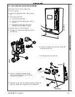
Page 37: ...ol panel undo the two retaining screws and withdraw the panel 4 Remove the fan unit Refer to Frame 53 5 Disengage the low pressure sensing pipe from the manifold block 7 Undo the gas cock union connection 6 Undo the 2 retaining screws and unplug the electrical leads from the gas valve 9 Supporting the valve undo the 3 retaining screws and withdraw the gas valve complete with mounting bracket and m...

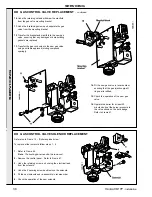
Page 38: ...6 Check the operation of the new solenoid 14 Fit the new gas valve in reverse order ensuring that the gas injection pipe O ring seal is refitted 15 Check the operation of the new gas valve 16 Operate the boiler for at least 20 minutes and set the burner pressure to the value shown on the data badge Refer to Frame 47 10 Undo the retaining nut and withdraw the manifold from the gas valve mounting br...

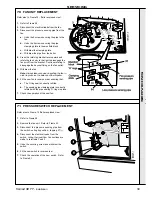
Page 39: ...58 2 Disconnect the electrical leads from the fan 3 Disconnect the pressure sensing pipe from the fan a Undo the 2 screws securing the pipe to the fan b Undo the 2 screws securing the pipe clamping plate to the manifold block c Withdraw the clamping plate d Withdraw the pipe from the boiler 4 Press the retaining bracket lever upward and rotate the fan body to the right to disengage the fan scroll ...

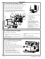
Page 40: ...n tilt forward and withdraw it from the boiler 8 Fit the new siphon and reassemble in reverse order replacing any damaged or deteriorating sealing gasket Refer also to Frame 10 Boiler exploded view and Frame 37 Pictorial wiring 1 Refer to Frame 58 Note The sealing panel need not be removed 2 Remove the boiler bottom panel Refer to Frame 59 step 4 3 Open the controls pod door and pull off the therm...

Page 41: ...for damage and replace if necessary 19 Lower the heat exchanger to disengage from the flue connector tube and withdraw it from the boiler 20 Fit the new heat exchanger and re assemble in reverse order IMPORTANT The flow and return bosses are not common and MUST be refitted in their correct positions The FLOW connection boss has a COARSE thread The RETURN connection boss has a FINE thread Flow pipe...

Page 42: ...r to Frame 58 2 Remove the old seal from the casing and thoroughly clean the casing surfaces 3 Fit the new self adhesive seals 4 Re assemble in reverse order Note Ensure that the boiler sealing panel is correctly seated compressing the sealing strip to make an airtight joint SERVICING 2 ...

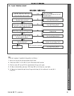
Page 43: ...MENU YES but only for a few seconds Note The correct sequence of operation during ignition is as follows 1 Mains to boiler with all boiler thermostats calling for heat 2 If the fuse on PCB 37 is OK LEDs 2 3 and 4 illuminate and the fan starts 3 After 8 seconds LED 2 goes OFF the spark starts and the gas valve opens 4 If a flame is detected the spark stops LED 2 stays OFF and the Burner on neon lig...

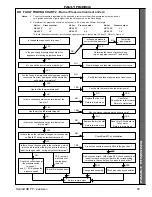
Page 44: ...no fault found check Board 37 by substitution YES NO YES Return to main menu The fan should now run Has fuse blown on Board 37 Fuse is OK if LED 4 is lit YES Is there mains voltage on BOTH terminals of boiler control thermostat YES YES Reset overheat stat Set control stat to maximum Allow boiler to reach temperature If overheat stat trips again measure flow temp If over 90 C replace control stat I...

Page 45: ...f OK change the pressure switch NO YES YES but only with the boiler sealing panel removed Is there live on the connector in the control box which joins the red lead from the dry fire stat to the brown lead from the gas valve during an ignition trial period Remove connectors With mains OFF check continuity of leads from each socket unit back to the corresponding terminals in the control box Are lea...

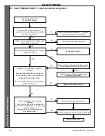
Page 46: ...e tags Rectify faulty connection YES Fan and gas supply OK Ignition spark suspect Re assemble and restore gas supply Boiler should now light and Burner on neon illuminate FAULT FINDING FAULT FINDING Return to Main Menu Is there mains voltage on Board 37 terminals for the spark generator during the 5 ignition trial periods Rectify poor connections or replace spark generator or electrodes NO YES YES...

Page 47: ... from the burner Exit 82 FAULT FINDING CHART 4 Flame Detection FAULT FINDING FAULT FINDING YES Boiler lights briefly then goes off leaving LED2 on the PCB lit Is polarity of the supply correct Ensure that live is connected to L and neutral to N YES Check all connections on Board 37 If no fault found check Board 37 by substitution Boiler should now light Re assemble the boiler Does the boiler now l...

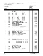
Page 48: ...CB No 37 1 111748 10 308 556 Spark generator assembly PACTROL 1 112 216 11 378 933 Control thermostat RANCO K36P1331 1 111 853 12 382 873 Overheat thermostat ELMWOOD 2455 RM 98727 1 076 817 13 378 934 Dry fire thermostat RANCO LM7 P5077 1 111 854 14 378 935 Flue thermostat ELMWOOD 1 138 097 15 308 591 Siphon assembly ALTEKNIC 1 076 819 16 308 557 Control thermostat knob 1 111 904 17 308 558 Fan as...

Page 49: ...d No 37 11 Boiler control thermostat 16 Thermostat knob LEGEND A O ring B Gasket 1 Burner 2 Burner injector 3 Gas valve 5 Detection electrode 6 Ignition electrode 17 Fan 84 CONTROL BOX ASSEMBLY Exploded view 23 Low pressure sensing pipe 24 Fan pressure sensing pipe 37 Gas valve mounting bracket 40 Sensing pipe clamping plate 42 Burner mounting flange ...

Page 50: ...ce December 1999 UIN 153 960 A02 Technical Training Caradon Plumbing Limited P O Box 103 National Ave Kingston upon Hull HU5 4JN T elephone 01482 492 251 Fax 01482 448 858 Registration No London 322 137 Registered Office National Avenue Kingston upon Hull HU5 4JN A subsidiary of Caradon p l c The Caradon Plumbing Limited Training Centre offers a series of first class training courses for domestic ...

Page 51: ...your suggestions for how to improve our boilers and our service We ll be giving away a free boiler for the five best ideas every year to be selected by our Technical Director Please complete this form using extra sheets if required and post it or fax it to us on 01482 498699 Boiler details Model Size details on control panel door Date of Installation Installer details Name Address Post Code Teleph...

Page 52: ...neral information required Please send me details of Henrad Training Courses Please arrange for a technical representative to contact me Please arrange for me to join a Henrad factory tour Range guides required The Henrad Guide a specifier s and installer s introduction to the Henrad domestic boiler range The Henrad Householders Guide to assist the installer when presenting to his her customers Te...

Reviews: