background image

3

icos system - 

User's

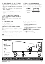
Legend

A

Boiler ON/OFF switch

B

Mains on neon

C

Display

D

Reset button

E

LED

F

CH thermostat knob

G

Condensate drain

H

Pressure gauge

A

B

F

D

E

C

H

G

2093

To light the boiler. Refer to Frame 1

If a programmer is fitted  refer to separate instructions for the
programmer before continuing.

1.

CHECK THAT THE ELECTRICITY SUPPLY TO THE BOILER
IS OFF.

2.

Set the mains ON/OFF switch (A) to OFF and the thermostat
knob (F) to maximum.

3.

Switch ON the electricity supply to the boiler and check that
all external controls, e.g. programmer, room thermostat, etc.,
are ON.

4.

Set the mains ON/OFF switch to ON.

The mains on neon (B) will illuminate and the boiler will
commence the ignition sequence, supplying heat to the central
heating, if required.

Note.

In normal operation the control unit display (G) will show

the codes:

Standby - no demand for heat.

CH being supplied.

During ignition, the LED (E) will flash.

During normal running the LED (E) will remain illuminated.

Note.

If the boiler fails to light after 3 attempts the fault code     will be
displayed.

Press the reset button (D) for 2 seconds then release. The boiler
will repeat the ignition sequence. If the boiler still fails to light
consult a CORGI registered installer.

Note.

The pump will operate briefly as a self-check, once every 24
hours regardless of system demand.

CAUTION. 


To avoid the possibility of injury during the installation, servicing or cleaning of

this appliance care should be taken when handling edges of sheet steel components.

1

BOILER controls

Control of water temperature

The boiler controls the central heating radiator temperature to a
maximum of 82

o

C, adjustable via the thermostat knob (F).

To shut down the boiler

1. For short periods

Set the mains ON/OFF switch (A) to OFF

2. For longer periods

Set the mains ON/OFF switch (A) to OFF, and switch the
electricity supply to OFF.

For longer periods the entire system should be drained.

To relight the boiler

Repeat the procedure detailed in 'To light the boiler'.

Approx. flow temperatures for the boiler thermostat settings are:

Knob Setting

Flow Temperature

°C

°F

Minimum

43

110

Maximum

82

180

Summary of Contents for icos system m3080

Page 1: ......

Page 2: ...Table 2 Performance Data Central Heating m3080 Boiler Input Nett CV kW Btu h Gross CV kW Btu h Gas Consumption l s ft3 h Boiler Output Non Condensing kW Btu h Condensing kW Btu h Key to symbols IE Ireland Countries of GB United Kingdom destination PMS Maximum operating pressure of water C13 C33 C52 A room sealed appliance designed for connection via ducts to a horizontal or vertical terminal which...

Page 3: ...Diagrams 22 to 25 icos system Natural Gas only G C Appliance No 41 391 52 PI No 0063BM9802 Destination Countries UK IE NOTE TO THE INSTALLER LEAVE THESE INSTRUCTIONS ADJACENT TO THE GAS METER ALSO COMPLETE THE BENCHMARK LOG BOOK AND GIVE THIS TO THE CUSTOMER BENCHMARK LOG BOOK DETAILS Boiler Page Make and model 3 Appliance Serial No on Data Badge 3 Controls as applicable Forall boilers Flushing to...

Page 4: ... places Pipework from the boiler is routed downwards as standard but may be routed upwards behind the boiler using the stand off frame supplied in a separate kit Expansion vessel Automatic air vent Heat engine Gas valve Pump Safety relief valve Condensate s trap Water pressure gauge Sump Fan Burner Flow Gas Condensate drain Discharge pipe Ecl 2063 Return OPERATION When there is a demand for heat t...

Page 5: ...f a control device not approved by Caradon Ideal Limited could invalidate the certification and the normal appliance warranty It could also infringe the Gas Safety Regulations and the above regulations SAFE HANDLING OF SUBSTANCES Care should be taken when handling the boiler insulation panels which can cause irritation to the skin No asbestos mercury or CFCs are included in any part of the boiler ...

Page 6: ...de and Rear Flue a Provided that the flue hole is cut accurately e g with a core drill the flue can be installed from inside the building where wall thicknesses do not exceed 600mm 24 Where the space into which the boiler is going to be installed is less than the length of flue required the flue must be fitted from the outside Installation from inside ONLY b If a core boring tool is to be used ins...

Page 7: ...eating system should be in accordance with BS 6798 and in addition for smallbore and microbore systems BS 5449 Draining taps MUST be located in accessible positions which permit the draining of the whole system They should be at least 1 2 BSP nominal size and be in accordance with BS 2879 WATER TREATMENT see Frame 6 GAS SUPPLY The local gas supplier should be consulted at the installation planning...

Page 8: ...estrict water circulation and inhibit the condensing mode of condensing boilers reducing fuel economy For further information refer to the Good Practice Guide 143 a publication of the Energy Efficiency Office available from the Building Research Establishment Garston Watford WD2 7JR Tel 01923 664258 ELECTRICAL SUPPLY Wiring external to the appliance MUST be in accordance with the current I E E BS ...

Page 9: ...ressurisation of the system The maximum cold water capacity of the system should not exceed 143 litres if not pressurized However if the system is to be pressurized the efficiency of the expansion vessel will be reduced and a larger vessel or smaller system volume may be necessary If the capacity of the vessel is not considered sufficient for this or for any other reason an additional vessel MUST ...

Page 10: ...hich must be used in accordance with the manufacturers instructions For further information contact Fernox Manufacturing Co Ltd Sentinel Division Betz Dearborn Ltd Widnes Cheshire WA8 8UD Tel 0151 424 5351 Tandem House Marlowe Way Croydon Surrey CRO 4XS Tel 0870 5601 5000 Notes 1 It is most important that the correct concentration of the water treatment product is maintained in accordance with the...

Page 11: ...densing Installation and Servicing INSTALLATION 7 BOILER ASSEMBLY Exploded View 44 5 53 8 14 13 21 62 64 4 2 63 1 61 70 69 35 36 24 23 32 17 12 20 11 26 25 42 19 6 58 Ecl 2065 16 15 22 9 10 39 75 51 57 3 18 INSTALLATION ...

Page 12: ...ibre washers 2 off Pack A Contents Also contained in Pack A z Hardware Pack listed below z These Installation Servicing Instructions z The User s Instructions z The User Control z Benchmark log book 1 Ensure the boiler is stood correctly as marked on the carton 2 Remove the strapping 3 Fold back the top flaps to gain access to the wall mounting plate instructions hardware pack and user control 4 R...

Page 13: ...H AND FLUE PACKS REQUIRED Notes 1 The flue duct MUST be inclined at 1 5 degrees to the horizontal to allow condensate to drain back into the boiler and out through the condensate drain 2 If the boiler is to be installed with upward piping routed behind the boiler then the optional stand off kit should be used Care must be taken when cutting the ducts and marking wall to suit this condition Total F...

Page 14: ...ote Mark the centre of the hole as well as the circumference 4 Remove the template from the wall 13 WALL MOUNTING TEMPLATE 12 FLUE ASSEMBLY Exploded View LEGEND 1 Duct assembly 2 Flue Turret 3 Turret seal 4 M5 x 10 pozi screw 5 Turret clamp 1 An optional flue duct extension kit is required for wall thicknesses greater than Side 300mm 11 3 4 Rear 345mm 13 1 2 Rear flue arrangement shown Note Side f...

Page 15: ... at each side and screw home 15 CUTTING THE FLUE REAR Wall thicknesses of 114 to 345mm Note a If using the extension ducts go to Frame 21 b If the upward routing pipe stand off brackets are used it is essential add 33mm to X the measured wall thickness when marking the flue this will allow for the fitted brackets 1 Measure and note wall thickness X Refer to Frame 11 2 Add 75mm 3 to dimension X and...

Page 16: ...ame To allow pipework to be taken upwards z z z z z Insert wall plugs z z z z z Put the screws into the wall plugs and leave 10mm proud z z z z z Hang the stand off frame onto the screws and tighten up z z z z z Fasten the piping frame to the stand off frame with the 6mm screws and washers provided z z z z z Locate the support bracket on the piping frame Note If the clearances above and below the ...

Page 17: ... the control box Refer to Frame 33 10 Swing the control box back into its working position and secure 11 Screw the user control into position 19 CONNECTING THE FLUE TO THE BOILER Note a BEFORE fitting the flue turret fill the condensate trap within the boiler by pouring a cupful of water into the flue outlet A b Take care to ensure that the water is only poured into the flue outlet and does not sp...

Page 18: ...ges 23 FITTING THE KIT 21 FLUE EXTENSION DUCTS For flue lengths greater than 480mm Pack D Flue extension duct kit contents Note Side flue shown General arrangement 20 TERMINAL WALL PLATE optional This plate is supplied in the Flue Finishing Kit together with one inner and one outer flue seal it allows neat concealment and full compression of the outer seal if fitted Its use is not essential if the...

Page 19: ... the wall If pipes are run vertically within the boiler back space provided by optional stand off frame positions they must avoid any obstructions imposed by the channels and by a rear facing flue should this position be selected 24 SERVICE CONNECTIONS 2 Horizontal connecting pipes where used must be run outside the limits of the boiler casing 2070 22mm copper pipe Isolating valve shown in the ope...

Page 20: ... within the dwelling IMPORTANT Any external runs must be insulated Excessive external pipe runs should be avoided in order to prevent possible freezing All pipework and fittings in the condensate drain system must be made of plastic No other materials may be used The drain outlet on the boiler is standard 21 5mm overflow pipe This size must not be reduced in any part of its length In order to defe...

Page 21: ...PORTANT when filling a The cap on the automatic air vent refer to Frame 68 MUST be loose at all times When filling there may be a slight water leak from the vent therefore electrical connections should be protected b Bleed any air from the pump and ensure that it is free to rotate i Remove the vent plug ii Using a screwdriver rotate the shaft several times iii Replace the vent plug Note Some sligh...

Page 22: ...act separation in both poles or a plug and socket serving only the boiler and system controls The means of isolation must be accessible to the user after installation WARNING This appliance MUST be earthed A mains supply of 230 V 50 Hz is required The fuse rating should be 3A Wiring external to the boiler MUST be in accordance with the current I E E BS7671 Wiring Regulations and any local regulati...

Page 23: ...left in the running position The frost thermostat should be sited in a cold place but where it can sense heat from the system Note If the boiler is installed in a garage it may be necessary to fit a pipe thermostat preferably on the return pipework Wiring should be as shown with minimal disturbance to other wiring of the programmer Designation of the terminals will vary but the programmer and ther...

Page 24: ...thermistor Overheat thermostat Control thermistor Gas valve Pump User control and display ON OFF Switch Service connection MAINS SUPPLY 230V 50Hz Fan y y Chassis earth y g Ecl 1990 Fused at 3 15ATL y y Filter Permanent black link Control PCB PHC 033 33 PICTORIAL WIRING DIAGRAM LEGEND b blue bk black br brown r red pk pink y yellow w white y g yellow green gy grey or orange v violet INSTALLATION ...

Page 25: ... 1 The whole of the gas installation including the meter should be inspected and tested for soundness and purged in accordance with the recommendations of BS 6891 2 Purge air from the gas installation by approved methods only 3 Retighten the union and test for gas soundness 35 COMMISSIONING AND TESTING bk or or v v Pump p br y g b y g DC Gas valve Overheat thermostat b r br Mains Switch DC Fan r b...

Page 26: ...Frame 45 and screw the control into position 11 Switch the electricity supply ON and check all external controls are calling for heat The display The user control has one LED and one display to inform the user about the status The display will show the status of the boiler The LED will show the status of the flame If no flame is detected the LED is blinking When the flame is detected the LED will ...

Page 27: ...ce air flow reducing the gas rate slightly If these rates are not obtainable consult the fault finding section 3 Set the external controls to OFF The burner should go off and the pump continue to run for a few seconds The display should read returning to when the pump stops 4 Check the correct operation of the programmer if fitted and all other system controls Operate each control separately and c...

Page 28: ...er As the installer you may wish to undertake the service contract yourself or alternatively offer to the customer the benefits of the Ideal Care Scheme details of which are outlined in the householder pack supplied with this boiler After completing the installation and commissioning of the system the installer should hand over to the householder by the following actions 1 Hand the User Instructio...

Page 29: ...5 but see note above 5 Clean the main burner 6 Clean the heat engine Note This must be done with the heat engine and deposits in a dry condition refer to Frame 49 7 Check the main injector for blockage or damage 8 Wherever possible remove and clean the condensate trap refer to Frame 48 and check the drain for blockage 9 Check that the flue terminal is unobstructed and that the flue system is seale...

Page 30: ...nd side of the panel down slide it to the right and withdraw 45 THE CONTROL PANEL IN THE SERVICING POSITION 1 Swing the control panel down into the servicing position a Remove the 2 securing screws and withdraw the user control b Unplug the low voltage electrical lead from the back of the user control c Unplug the spark lead from the bottom of the control box d Turn the clamp swing the control box...

Page 31: ... are extended to ease access 2 Lift off the burner from the combustion chamber WARNING The burner head is a ceramic plaque construction Care must be taken to ensure that the burner is not placed down upon its face as this may cause damage to the ceramic 3 Brush off any deposits that may be on the ceramic with a SOFT brush 4 Inspect the sealing gasket around the burner for any signs of damage Repla...

Page 32: ...he sump 5 Inspect the spark and detection electrodes Ensure that they are clean and in good condition replace if necessary 6 Check that the spark and detection gaps are correct 7 Check the spark and detection leads are in good condition and renew as necessary Note Take care not to disturb the detection earth probe at the rear of the combustion chamber IMPORTANT Ensure that the boiler sealing panel...

Page 33: ...he fan 4 Undo the gas pipe union connection to the injector housing 5 Remove the retaining screw and pull off the mounting bracket 6 Remove the fan and venturi assembly 7 Remove the 3 retaining screws and remove the venturi assembly noting the orientation of the venturi in relation to the fan body 8 Transfer the venturi assembly to the new fan replacing the gasket if evidence of damage or deterior...

Page 34: ...ing panel Refer to Frame 44 3 Unscrew the 2 sight glass retaining screws 4 Remove the sight glass gasket and bracket 5 Fit new sight glass using the new bracket and gasket supplied 6 Re assemble in reverse order 7 Check operation of the boiler Refer to Frame 51 56 BURNER REPLACEMENT 1 Refer to Frame 51 2 Remove the boiler sealing panel Refer to Frame 44 3 Remove the fan Refer to Frame 53 4 Remove ...

Page 35: ...on chamber 6 Unbolt the sensing electrode earth lead from the earth point beneath the boiler 6 Remove the electrode taking care not to dislodge the grommet from the casing 7 Fit the new ignition electrode using the new gasket supplied check dimensions as shown 8 Re assemble in reverse order 9 Check the operation of the boiler Refer to Frame 51 7 Remove the electrode complete with grommet 8 Fit the...

Page 36: ...the spare part Gloves supplied with the spare part 7 Remove the detection earth probe 8 Damp down the combustion chamber area containing the insulation boards 9 Remove the split pin and washer from the RHS of the combustion chamber 10 Remove the insulation boards The replacement boards are supplied in a plastic bag This bag should be retained and the discarded boards should now be placed into it 1...

Page 37: ... pipe 9 Fit the new valve and re assemble in reverse order 10 Check operation of the boiler Refer to Frame 51 Securing screw slacken do not remove Earth wire Electrical lead Sensing tube Mounting bracket Gas inlet pipe union A Union nut B 2038 62 CONDENSATE S TRAP REPLACEMENT 1 Refer to Frame 51 2 Remove the casing bottom panel Refer to Frame 43 3 Swing the control panel down into the servicing po...

Page 38: ...he control box from the hinge arms Refer to diagram C 6 Unplug all the electrical wiring from the control box and remove 7 Re assemble in reverse order ensuring that the control box is located correctly in the housing before reconnecting the electrical wiring 8 Check operation of the boiler Refer to Frame 51 1 Refer to Frame 51 2 Remove the 2 securing screws and allow the user control to lower 3 P...

Page 39: ... Re assemble in reverse order 6 Check operation of the boiler Refer to Frame 51 65 USER CONTROL REPLACEMENT 66 PRESSURE GAUGE REPLACEMENT 1 Refer to Frame 51 2 Drain the boiler Refer to Frame 69 3 Unscrew the pressure gauge and discard 4 Fit the new pressure gauge using a suitable jointing compound 5 Refill the boiler Refer to Frame 29 6 Check operation of the boiler Refer to Frame 51 2041 Pressur...

Page 40: ...r vent complete with O ring provided and re assemble in reverse order Note In the event that the extension pipe is removed at the same time as the air vent remove it from the air vent and refit it into the heat exchanger ensuring that its O ring seal is in place before fitting the new air vent IMPORTANT Ensure that the vent cap is loose A housing 6 Withdraw the securing pin 7 Remove the safety val...

Page 41: ... head 9 Re assemble in reverse order 10 Check operation of the boiler Refer to Frame 51 69 DRAINING THE BOILER 1 Refer to Frame 51 2 Remove the boiler bottom panel Refer to Frame 43 3 Close all the water isolating valves on the piping frame 4 Attach a length of hose to the drain point and open the drain valve 5 After replacing any component on the boiler close the drain valve remove the hose and o...

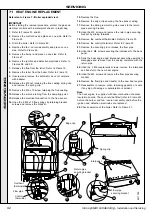
Page 42: ...ctrical connection to the flue sensor 14 Undo the 2 M5 x 10 flue spring clip retaining bracket screws and remove the bracket 71 HEAT ENGINE REPLACEMENT 15 Remove the flue 16 Remove the edge clip securing the flue sensor wiring 17 Remove the blind grommet to gain access to the return pipe securing bracket 18 Undo the M5 screw and remove the return pipe securing bracket by sliding forwards 19 Remove...

Page 43: ... 69 3 Undo all the gas and water connection unions on the boiler side of the valves 4 Remove the turret screw and remove the turret clamp 5 Remove the turret 6 Lift the complete boiler from the wall mounting frame and place on a flat surface face down to expose the expansion vessel 7 Undo the union nut on the vessel water connection pipe 8 Remove the 2 screws and remove the securing clamp 9 Remove...

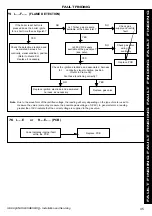
Page 44: ...TO FRAME 75 ALTERNATING L E GO TO FRAME 76 ALTERNATING L A GO TO FRAME 77 ALTERNATING L 8 GO TO FRAME 78 ALTERNATING H 1 GO TO FRAME 79 ALTERNATING H 4 GO TO FRAME 80 ALTERNATING H F GO TO FRAME 81 In order to assist fault finding the boiler has an LED diagnostic display The key to the display codes is as follows ALTERNATING H n GO TO FRAME 82 ALTERNATING H E GO TO FRAME 76 ...

Page 45: ... is pressed does the boiler ignite for a short time then extinguish Is 200 V DC supply available at the gas valve see note NO YES YES Is 17mbar gas pressure available at the boiler inlet Replace PCB Check gas supply and rectify fault Replace ignition electrode and associated harness as necessary NO Replace gas valve YES NO NO 76 L E or H E PCB Code indicates internal fault within the PCB Replace P...

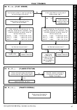
Page 46: ...er and all isolation valves open OK NO YES NO Replace overheat thermostat 78 L 8 FAN Is nominal 330 V DC present across red and blue at the fan connector as reset button is pressed Replace fan YES NO Replace harness 79 H 1 CONTROL TEMPERATURE SENSOR YES Is there continuity between the PCB and the thermistor Check resistance The sensors can be checked by measuring their resistance using a suitable ...

Page 47: ...r values correct Replace PCB Replace thermistor Fill and vent the system and open all isolating valves YES Check resistance The sensors can be checked by measuring their resistance using a suitable multimeter connected across the sensors terminal pins At 25 o C expect 9 700 10 300 Ohms At 60 o C expect 2 400 2 600 Ohms At 85 o C expect 1 000 1 100 Ohms Are thermistor values correct Inspect heat ex...

Page 48: ...mber 1 E69 280 Front casing panel 1 170 994 4 E69 282 Bottom casing panel 1 170 987 11 E67 489 Burner 1 170 905 12 E67 490 Combustion chamber insulation 1 170 906 14 E67 492 Injector and housing 1 170 908 16 E67 494 Fan assembly 1 170 909 17 E69 286 Automatic air vent 1 170 988 19 E69 288 Gas control valve Honeywell VK4115V 1 171 035 22 E67 500 Dry fire thermostat 1 170 916 23 E67 501 Control ther...

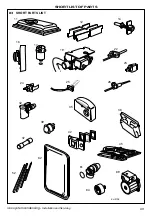
Page 49: ...49 icos system condensing Installation and Servicing SHORT LIST OF PARTS 83 SHORT PARTS LIST Ecl 2106 35 45 52 16 19 39 37 25 22 12 11 23 26 69 64 61 62 17 42 14 32 24 36 ...

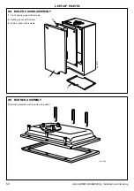
Page 50: ...lation and Servicing LIST OF PARTS 84 BOILER CASING ASSEMBLY 85 BURNER ASSEMBLY 1 Front casing panel with screws 2 Sealing panel with screws 4 Bottom panel with screws 11 Burner assembly with screws and gasket Ecl 2101 1 4 2 Ecl 1598 ...

Page 51: ...51 icos system condensing Installation and Servicing NOTES ...

Page 52: ... without notice The Ideal Boilers Technical Training Centre offers a series of first class training courses for domestic commercial and industrial heating installers engineers and system specifiers For details of courses please ring 01482 498 432 CERTIFIED PRODUCT Manufactured under a BS EN ISO 9001 1994 Quality System accepted by BSI The code of practice for the installation commissioning servici...

Page 53: ......

Page 54: ...ng correctly fitted and forming an adequate seal z z z z z If the boiler is installed in a compartment then the compartment MUST NOT be used for storage purposes z z z z z If it is known or suspected that a fault exists on the boiler then it MUST NOT BE USED until the fault has been corrected by a CORGI registered installer z z z z z Flammable materials must not be placed in close proximity to the...

Page 55: ...lluminated Note If the boiler fails to light after 3 attempts the fault code will be displayed Press the reset button D for 2 seconds then release The boiler will repeat the ignition sequence If the boiler still fails to light consult a CORGI registered installer Note The pump will operate briefly as a self check once every 24 hours regardless of system demand CAUTION To avoid the possibility of i...

Page 56: ...eserved to vary specification without notice April 2001 UIN 156415 A01 The code of practice for the installation commissioning servicing of central heating systems Caradon Plumbing Ltd is a member of the Benchmark initiative and fully supports the aims of the programme Benchmark has been introduced to improve the standards of installation and commissioning of central heating systems in the UK and ...

Reviews: