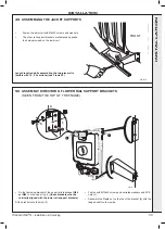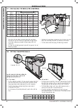
35
Viscount GTS -
Installation & Servicing
INSTALLATION
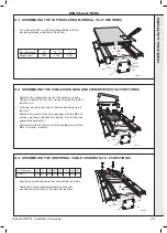
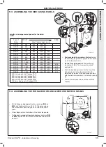
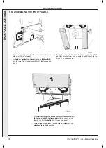
53 ASSEMBLING THE SIDE CASING PANELS
1
2
4
5
2
3
VIS5114
Length and arrangement of panels for the boiler
model
•
First assemble the panels on the front
using
the assembly length table opposite and continue
up to the rear section (1).
•
Fix the front side panels
to the positioning
brackets with M8 x 16 screws and serrated
washers (2).
• Push the insulating material into the top of the
side panels and fasten the panels (3) to the
lower rails by means of the self-tapping screws
with the electric screwdriver (2 screws per panel)
(4).
• Fasten the side panels to each other with the
clips (5).
Type of
Boiler
GTS 14
800
600
600
GTS 15
940
600
600
GTS 16
1050
600
600
GTS 17
940
600
400
400
GTS 18
1050
600
400
400
GTS 19
940
600
600
400
GTS 20
940
600
600
600
GTS 21
1050
600
600
600
GTS 22
940
600
600
400
400
GTS 23
1050
600
600
400
400
GTS 24
940
600
600
600
400
GTS 25
1050
600
600
600
400
400 mm long panel in Package FA10
600 mm long panel in Package FA11
800 mm long panel in Package MR 3
940 mm long panel in Package MR4
1050 mm long panel in Package MR5
Side Panels Length in mm
FRONT
REAR
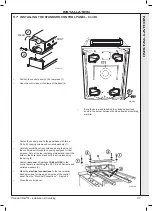
•
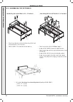
Put the
furnace door panel
in place (package
IG84 or
IG85
) and fasten with two ø 3.94 x 12.7 tapping screws.
The furnace door panel may be cut in two at the micro-
joints.
• Fit two Rapid nuts in the bottom of the front side panels.
• Fix
the casing support lower crosspiece
(package
IG84
or IG85
) by means of two M6x20 screws and two serrated
washers.
VIS5115
1
2
54 ASSEMBLING THE FURNACE DOOR AND LOWER CROSSPIECE PANELS
INST
ALLA
TION


