11
idealheating.com
10
welcome to our ideology
SUGGESTED ENGINEERING SPECIFICATION
OVERVIEW
The boilers must be fully automatically controlled, wall
mounted, fanned, super-efficient condensing appliances
utilising an aluminium silicon alloy heat exchanger and be
suitable for connection to fully pumped open vented or
sealed water systems.
CONTROLS
The condensing boilers must have connectivity for all
common types of BMS integration including 0-10v, volt free
and OpenTherm connections. Additional modules may
be used for BACnet, LONWorks and MODBus gateways.
Where no BMS is present a modulating sequencer must be
available.
The boiler must be fully modulating with a 5:1 turndown ratio
and include control features enabling set point adjustment,
heating circuit control of one constant temperature and one
DHW circuit or 2 constant temperature circuits, and safety
lock out parameters including fault diagnosis for both boiler
and external components such as sensors or pumps.
Boiler capabilities must include, with the use of
external components, frost protection, weather or room
compensation and system pump control.
FLUE
The condensing boilers must be suitable for use with a room
sealed flue or open flue applications including C13, C33 and
B23 classifications. The combined flue outlet and air inlet
must be situated on the top of the boiler.
HYDRAULIC
The condensing boiler must be and be suitable for
connection to fully pumped open vented or sealed water
systems. All hydraulic connections including flow return and
condensate drain must be located on the bottom of the
boiler. Hydraulic connections must be uniform across the
outputs available in the range to ensure ease of installation
and maintenance in mixed output cascades. The boiler must
have a maximum operating pressure of 6 bar and be suitable
for heating and indirect hot water systems.
DIMENSIONS
The condensing boiler range must have a universal compact
width and height across the range to ensure mixed output
cascades maintain the same universal configuration.
Maximum permitted wall area of 0.43m
²
.
MOUNTING
The condensing boilers can be installed either on the wall or
into a prefabricated floor mounted frame. Wall brackets must
be located at the top of the boiler and visible from the front
to aid installation.
EFFICIENCY
The condensing boilers are capable of high seasonal
efficiencies with a minimum requirement of 96.2% and low
NOx emissions no greater than 39.8mg/kWH for natural gas
and 80mg/kWH for LPG.
30, 40 and 60kW models must have a Seasonal Space
Heating Energy Efficiency of A.
APPROVALS
The boiler must be tested and certified to; EN 483, EN 677,
PREN 15420, BSEN 15417, BSEN 656, BSEN 60335-2-102, BSEN
55014-1 and BSEN 55014-2 for use with Natural Gas. Boilers are
certified to meet the requirements of the EC Gas Appliance
Directive, Boiler Efficiency Directive, EMC and Low Voltage
Directive.
The manufacturer must be ISO 9001 accredited.
SPECIFICATION
•
The 30kW boiler will be capable of flow rates for common
systems using either 11°C, 15°C, 20°C or 25°C temperature
differentials.
• The 40, 60 and 80kW boiler will be capable of flow rates for
common systems using either 11°C, 15°C, 20°C, 25°C or 30°C
temperature differentials.
• The 100kW boiler will be capable of flow rates for common
systems using either 15°C, 20°C, 25°C or 30°C temperature
differentials.
• The 120 and 150kW boiler will be capable of flow rates
for common systems using either 20°C, 25°C or 30°C
temperature differentials.
SOURCING
The condensing boiler must be manufactured or finally
assembled in the United Kingdom.
CASCADE
The boiler must be configurable up to 6 boilers (max 900kW)
in cascade using a prefabricated frame and header kit.
WARRANTY
The boiler must be available with a 5 year warranty.
The Suggested Engineering Specification
is wording designed for specifiers to copy
and paste into their specifications to ensure
inclusion of Ideal Heating commercial boilers.
SYSTEM TEMPERATURE
DIFFERENTIALS
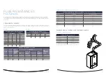
Flow rates for common systems using either 11
°
C, 15
°
C, 20
°
C, 25
°
C or 30
°
C temperature differentials
are given in the table below.
FLOW RATE (L/MIN)
HYDRAULIC RESISTANCE (MBAR)
BOILER
11°C
15°C
20°C
25°C
30°C
11°C
15°C
20°C
25°C
30°C
Evomax 2 30 / 30P
39.1
28.7
21.5
17.9
N/A
425
225
127
89
N/A
Evomax 2 40 / 40P
52.1
38.2
28.7
23.9
19.1
875
405
225
163
100
Evomax 2 60 / 60P
78.2
57.3
43.0
35.9
28.7
435
180
83
57
30
Evomax 2 80 / 80P
104.2
76.4
57.3
47.8
38.2
750
420
180
125
70
Evomax 2 100 / 100P
N/A
95.6
71.7
59.8
47.8
N/A
315
134
97
60
Evomax 2 120 / 120P
N/A
N/A
86.0
71.7
57.3
N/A
N/A
218
149
80
Evomax 2 150
N/A
N/A
107.5
89.6
71.7
N/A
N/A
230
158
85
• 30kW boilers must operate with temperature differentials from 11°C to 25°C.
• 40, 60 and 80kW boilers must operate with temperature differentials from 11°C to 30°C.
• 100kW boilers must operate with temperature differentials from 15°C to 30°C.
• 120 and 150kW boilers must operate with temperature differentials from 20°C to 30°C.
FLUE SYSTEMS
A comprehensive range of flue kits are available from
Ideal Heating including horizontal and vertical concentric and
open flue options.
For horizontal flues: this is the distance from the flue outlet
centre line on the boiler to the outside wall.
For vertical flue: this is the distance from the top of the boiler
case to the aperture in the weather collar. If elbows are to
be used, then the equivalent length of that fitting must be
subtracted from the maximum flue extensions allowed for that
flue option.
Note: Horizontal terminal resistance includes 1 x 90° elbow.
When installing Evomax 2 boilers with concentric flue
(horizontally or vertically) the Ideal commercial flue system
must be used.
The resistance of flue components, together with the
maximum flue resistance each boiler can work against, may
be used to calculate the total flue resistance of the system,
and to determine if they are acceptable to run on the boiler.
Multiple boilers may be installed with a common
flue header.
The flue system should be designed and supplied by a
specialist flue company. BS 6644 and IGEM UP10 provide
guidance on design and the drainage of condensate from flue
stack and headers. Condensate from a flue stack and header
must be collected and drained before entering
the boiler.
For Ventilation requirements, please refer to the
Installation Manual.
CONTROL KITS
VARICAN MODULE MASTER & SLAVE KITS
Enables cascade control from Evomax 2 boiler controls.
EXTENSION MODULE KIT
Capable of managing 2 mixing circuits. Multiple
modules can be used.
OPENTHERM ROOM CONTROL KIT
Timed control of central heating via OPENTHERM.
ROOM SENSOR KIT
Used with Extension Module Kit for CH control
TANK SENSOR KIT
Provides DHW temperature control. Also for use with
Extension Module Kit.
OUTSIDE SENSOR KIT
Provides weather compensation directly or with
Extension Module Kit.
HEADER FLOW TANK IMMERSION SENSOR KIT
Ensures boiler provides correct temperature to water in
header via immersed sensor
HEADER FLOW TANK STRAP ON SENSOR KIT
Ensures boiler provides correct temperature to water in
header via external sensor
SAFETY INTERLOCK KIT
Provides boiler shut down via an external signal.


