26
Installation and Servicing
Section 2 - Installation
INST
ALLA
TION
w
g
o
g/y
b
BOILER
L
N
MAINS IN
SL 1
E
L
N
E
L
N
E
CH
ON
R/S
ON
R/S
C/S
HW
ON
HW
OFF
C/S
ON
IN
OUT
FUSED
SPUR
TIMER
CH ON
L
N
HW ON
HW OFF
Y PLAN
VALVE
Logic Max System
2
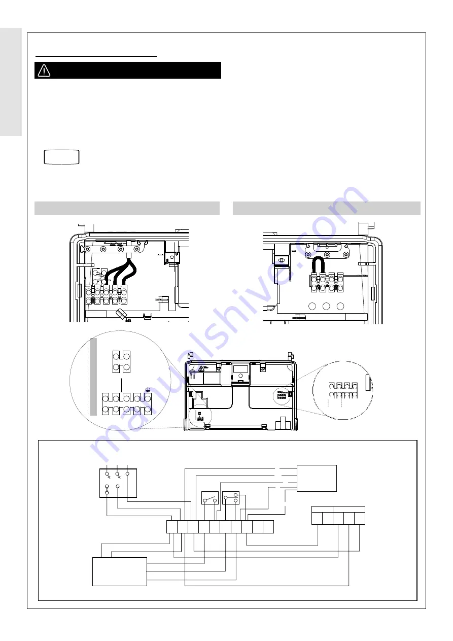
S BOILER WITH Y PLAN SYSTEM (without outside sensor)
Installer Connections (LHS)
Installer Connections (RHS)
Refer to Section
3.4
2.19 INSTALLER WIRING
The boiler must be connected to a permanent live power
supply.
Connecting the Switched Live to the Boiler
1.
Consult the Y Plan and S Plan diagrams overleaf.
2. Isolate the mains supply to the boiler
3.
Remove the front panel.
4. Swing down the control box into the service position,
unclip and swing back the installer wiring cover and
latch into the retaining clips.
All of the connections can now be readily accessed, the
plugs can be removed to aid wiring.
5. Connect the switched live to the terminal block as shown.
Note.
The cable strain relief system and grommets.
Once any wiring is completed, to secure the boiler, reverse
the order above.
FROST THERMOSTAT – WIRING
If parts of the system are vulnerable to freezing or the
programmer is likely to be left off during cold weather, a frost
stat should be fitted in conjunction with a pipe thermostat..
COMBI
HEA
T / SYSTEM
SL1
IN OUT
IN OUT
SL2
OPTIONAL
FROST STAT
ROOM
STAT/
TIMER L N
MAINS IN
UIN
230010 A01
L N
MAINS IN
COMBI
HEA
T / SYSTEM
SL1
L
IN
L
IN
SL2
OPTIONAL
FROST STAT
ROOM
STAT/
TIMER L N
MAINS IN
UIN
230010 A01
L N
MAINS IN
WARNING:
Ensure the supply cord is not damaged
OPEN THERM./
WEATHER COMP.
B


