6
IMAX XTRA 2 -
QAA55 Room Thermostat Kit Instructions
INSTRUCTIONS
1.6 CONNECTING THE QAA55 ROOM THERMOSTAT _ 3
Refer to the boiler manual for cable routing into the boiler.
Secure the cables with existing cable retention clamps or
cable tie slots that are on the boiler main control panel.
Ensure that isolation is maintained relative to 240V wiring.
Configuration of the Room Thermostat to the boiler occurs
during the configuration process described within the boiler
manual.
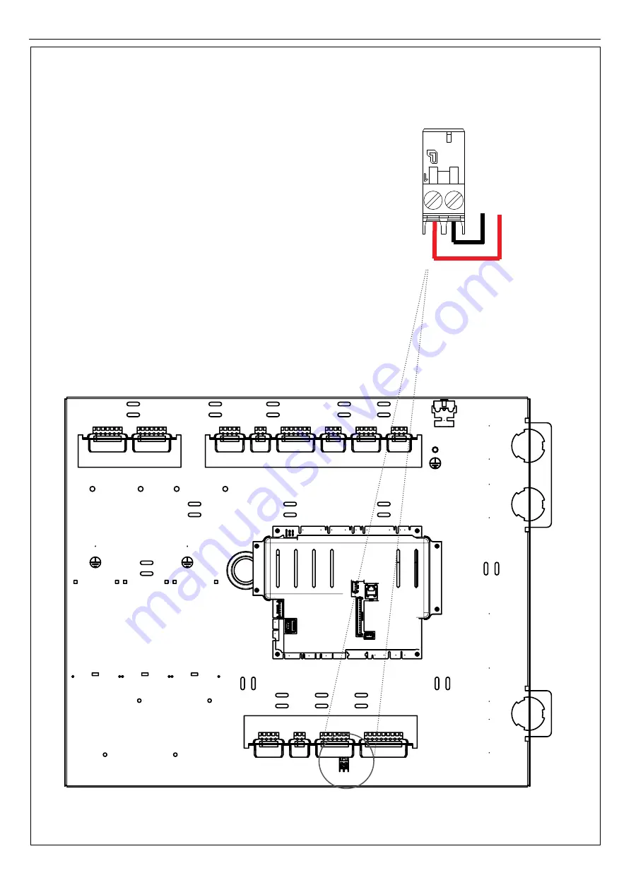
If the QAA55 Room Thermostat is required to run heating
zone 3 connect the wiring to I10_CN_C as follows:
1.
Connect the CL+ BSB Data red wire to pin 1 of
connector I10_CN_C
2.
Connect the CL- BSB Ground black wire to pin 2 of
connector I10_CN_C
These connections are shown Fig.11.
Insert connector I10_CN_C into Installer connector I10C,
as shown in Fig.12.
Fig. 11
Fig. 12
QAA55 -
QAA55 +
12
11
10
9
6a 6b
5
4
3
2
1
I
10_CN_C


