background image

33

Installation and Servicing


SECTION 2 - INSTALLATION

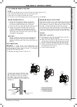
2.21  EXTERNAL ELECTRICAL CONTROLS

Wiring External to the Boiler

The fuse rating should be 3A.

Wiring external to the boiler MUST be in 
accordance with the current I.E.E. (BS 7671) 
Wiring Regulations and any local regulations.

Frost Protection

If parts of the pipework run outside the house or if 
the boiler will be left off for more than a day or so 
then a frost thermostat should be wired into the 
system.

The frost thermostat should be sited in a cold 
place but where it can sense heat from the 
system.

Note

.

  If the boiler is installed in a garage it may 

be necessary to fit a pipe thermostat, preferably 

on the return pipework.

EXAMPLE - Connection to Honeywell Evohome

(for additional information visit www.honeywelluk.com)

INST

ALLA

TION

Summary of Contents for VOGUE MAX SYSTEM 15IE

Page 1: ... not use reconditioned or copy parts that have not been clearly authorised by Ideal Heating For the very latest copy of literature for specification and maintenance practices visit our website idealheating com where you can download the relevant information in PDF format August 2021 UIN 223443 A03 INSTALLATION SERVICING VOGUE MAX SYSTEM 15IE 18IE 26IE 32IE ...

Page 2: ...ce Heating Full Load P4 kW 15 18 26 32 Part Load P1 kW 4 9 5 9 8 5 10 5 Auxiliary Electricity Consumption Full Load elmax kW 0 025 0 040 0 045 0 049 Part Load elmin kW 0 005 0 004 0 011 0 012 Standby PSB kW 0 003 0 003 0 003 0 003 Seasonal Space Heating Energy Efficiency Full Load ƞ4 89 6 89 8 89 7 89 8 Part Load ƞ1 97 0 97 8 97 8 97 8 Standby Loss Pstby kW 0 020 0 020 0 020 0 020 Ignition Pign kW...

Page 3: ...s VI Class VII Class VIII 1 2 1 5 2 3 4 3 5 5 PRODUCT FICHE The energy efficiency of the package of products provided for in this document may not correspond to its actual energy efficiency once installed in a building as the efficiency is influenced by further factors such as heat loss in the products in relation to the building size and its characteristics Collector Size in m2 Tank Volume in m3 ...

Page 4: ...4 Installation and Servicing ...

Page 5: ...e throughout from Ideal Boilers to Ideal Heating DOCUMENT AMENDMENTS Ideal Heating reserve the right to vary specification without notice FOR ANY TECHNICAL QUERIES PLEASE RING THE INSTALLER HELPLINE 00353 0 1 961 7700 NOTE BOILER RESTART PROCEDURE To restart boiler press RESTART button on the control panel The boiler will repeat the ignition sequence if a heat demand is present NOTES FOR THE INSTA...

Page 6: ...6 Installation and Servicing ...

Page 7: ...er 44 3 SERVICING 45 3 1 Servicing Schedule 45 3 2 Boiler Front Panel Removal Replacement 46 3 3 Lowering Controls Panel Accessing Mains Wiring 46 3 4 Fan And Venturi Assembly Removal And Cleaning 47 3 5 Removal Of Injector 47 3 6 Burner Removal And Cleaning 48 3 7 Cleaning The Condensate Trap Siphon 48 3 8 Cleaning The Heat Exchanger 49 3 9 Re Assembly 49 3 10 Replacement Of Components 50 3 11 Fa...

Page 8: ... been calculated have been certified by a notified body Boiler Input Max Min 15 IE 18 IE 26 IE 32 IE 15 IE 18 IE 26 IE 32 IE Boiler Input Q Nett CV kW 15 1 18 1 26 1 32 1 3 0 3 6 5 2 6 4 Gross CV kW 16 8 20 1 29 0 35 6 3 3 4 0 5 8 7 1 Gas Consumption m3 h 1 559 1 869 2 695 3 314 0 310 0 372 0 537 0 661 Boiler Output Non Condensing kW 15 0 18 0 26 0 32 0 3 0 3 6 5 2 6 4 70o C Mean Water temp Conden...

Page 9: ...ld water inlet temp measure record Hot water outlet temp measure record Water flow rate at max setting measure record For condensing boilers only Condensate drain 24 25 For all boilers complete sign hand over to customer For GB to comply with Building Regulations Part L1 Part 6 in Scotland the boiler should be fitted in accordance with the manufacturer s instructions Self certification that the bo...

Page 10: ...oid upper body top heavy bending Always grip with the palm of the hand Use designated hand holds Keep load as close to the body as possible Always use assistance if required 1 4 OPTIONAL EXTRA KITS Please visit idealheating com to access the Flue and Accessories Guide for this boiler 1 5 SAFETY Current Gas Safety installation and use regulations or rules in force The appliance is suitable only for...

Page 11: ...e local gas supplier should be consulted at the installation planning stage in order to establish the availability of an adequate supply of gas An existing service pipe must NOT be used without prior consultation with the local gas supplier The boiler MUST be installed on a gas supply with a governed meter only A gas meter can only be connected by the local gas supplier or by a Gas Safe Registered...

Page 12: ...emperature in a space served by radiators not fitted with such a valve When thermostatic radiator valves are used the space heating temperature control over a living dining area or hallway having a heating requirement of at least 10 of the minimum boiler heat output should be achieved using a room thermostat whilst other rooms are individually controlled by thermostatic radiator valves However if ...

Page 13: ...nimum front clearance when built in to a cupboard is 5mm from the cupboard door but 450mm overall clearance is still required with the cupboard door open to allow for servicing Bottom clearance Bottom clearance after installation can be reduced to 5mm This must be obtained with an easily removable panel to enable the consumer to access the filling loop and to provide the 100mm clearance required f...

Page 14: ...lume for the boiler expansion vessel If the capacity of the vessel is not considered sufficient for this or for any other reason an additional vessel MUST be installed on the return to the boiler Guidance on vessel sizing is given in table opposite 5 Filling The system may be filled by the following method Through a temporary hose connection from a draw off tap supplied from a service pipe under m...

Page 15: ...atment is also recommended by Ideal Heating Ideal Heating recommend Water Treatment in accordance with the Benchmark Guidance Notes on Water Treatment in Central Heating Systems If water treatment is used Ideal Heating recommend only the use of SCALEMASTER SM 1 PRO FERNOX MBI ADEY MC1 or SENTINEL X100 inhibitors and associated water treatment products which must be used in accordance with the manu...

Page 16: ...204 Gas Valve 205 Injector Gas 207 Venturi 208 Fan 209 Gasket Fan Venturi 210 Fan Adaptor 211 Venturi Deflector 212 Condensate Hose 213 Flue Turret Clamp 214 Siphon trap 217 Gas Cock 218 Flue Manifold 219 Flue Manifold Seal 220 Fan Adaptor Seal 302 Primay PCB 303 CUI Board 304 Thermistor Flow Return 306 Electrode Ignition 307 Electrode Detection 308 Ignitor Unit 317 Control Box Front 318 Control B...

Page 17: ...g Template located on internal protective packaging F Turret Clamp G Pressure Relief Valve Drain Pipe H Boiler Guarantee Registration Pack I Ideal System Filter C A D F G B E H Boiler Guarantee I Gas Valve Pack HARDWARE PACK CONTENTS Gas Valve Pack 1 Pipe Gas Inlet 2 Washer Gas blue 3 Gas Cock Return Valve Pack 1 Pipe CH Return 2 Washer CH 3 Valve Return Accessory Pack 1 Screw x2 2 Wallplug x2 3 T...

Page 18: ...Loosen the 2 screws retaining the front panel at the underside of the boiler 2 Release catches at rear of door by pulling downwards 3 Pull the underside front panel forward then lift upwards to remove 1 2 Note This flue system incorporates a removable flue outlet nose that utilises a push fit location system This enables the installation of deflector high level or balcony outlet flue kits without ...

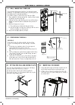
Page 19: ...ly with a 5 core boring tool ensuring that the hole is square to the wall Both wall faces immediately around the cut hole should be flat 2 Drill 2 mounting holes marked from template with a 7 5mm 8mm masonry drill and insert the plastic plugs provided for the wall mounting plate 3 Locate 2 No 14 x 50mm screws in the wall mounting plate one at each side in any of the 3 holes provided at each side a...

Page 20: ...itted in accordance to the installation instructions provided with them The TURRET supplied in the B Pack has an upper combustion sample point with a screw cap seal and a lower air sample point with an air stopper seal Ensure all caps seals are in place Additional Termination Kits available for use with these B packs Flue Deflector Kit The resistance is the equivalent of 1 metre of flue pipe and t...

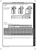
Page 21: ...scopic Horizontal Flue Terminal 1000mm long B Pack Telescopic Cut 75mm Minimum Maximum Minimum Maximum Minimum Maximum Minimum Maximum B Pack Standard 233 602 340 553 652 869 577 794 Plus 1 1m D pack 1183 1552 1290 1503 1602 1819 1527 1744 Plus 2 1m D pack 2133 2502 2240 2453 2552 2769 2477 2694 Plus 3 1m D pack 3083 3452 3190 3403 3502 3719 3427 3644 Plus 4 1m D pack 4033 4402 4140 4353 4452 4669...

Page 22: ... OFF THE TERMINAL END OF THE 1000MM TELESCOPIC FLUE ALL OTHER LENGTHS OBTAINED USING D PACK EXTENSIONS IN FLUE LENGTH TABLE 1 COLUMN HORIZONTAL FLUE TERMINAL 1000MM LONG B PACK CUT 75MM TELESCOPIC SHOULD HAVE THE 75MM CUT OFF THE D PACK EXTENSION AND NOT TELESCOPIC FLUE SETTING TELESCOPIC FLUE B PACK 1 Measure the required flue length A 44mm 2 Measure from the outer terminal lip to end of outer fl...

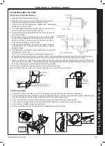
Page 23: ... from its mounting and will need to be refitted 9 When 1st mark is in line with the wall whilst holding the flue firmly push the white wall sealing flange to the wall until the 2nd of the two marks is just visible If the last location mark is clearly passed the white inner wall seal then the outer wall seal will have been dislodged from its mounting and will need to be re fitted 10 Ensure the seam...

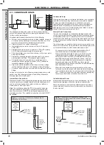
Page 24: ...er or pump manufacturer should be used terminating into a suitable internal foul water discharge point such as an internal soil and vent stack or internal kitchen or bathroom waste pipe etc fig 3 External Drain Connections The use of an externally run condensate drainage pipe should only be considered after exhausting all internal termination options as described previously An external system must...

Page 25: ...ernal pipe Water Weather proof insulation Max 3m external pipework Limestone chippings 500 300 25 2 rows of three Ø12mm holes 25mm centres 50mm from the bottom of the tube facing away from the house Minimum connection height up to 3 storeys Soil vent stack 450 Boiler with 75mm sealed condensate trap Min Ø 19mm Internal pipe Min Ø 30mm Internal pipe Water weather proof insulation Figure 3 Connectio...

Page 26: ...sing a separately supplied vertical connector WEATHER PROOFING Where the flue passes through the roof line an adequate seal must be made This is achieved by using either Flat roof weather collar or Universal weather collar ACCESSORIES Flue Duct Extension Kits are available for flue lengths extending beyond 1m These packs contain 1m extension ducts and may be cut to the desired length If the offset...

Page 27: ...penetrate the shaded area of the roof Note The equivalent flue length resistance of the elbow kits are 90o elbow kit 1m 45o elbow kit 0 6m If chimney penetrates dotted area such that A is less than 300mm B shall not be less than 300mm Where two or more vertical fanned draught chimney configurations terminate in close proximity at the same height they shall be separated by at least 300mm Where any ...

Page 28: ...ided with the vertical connector kit 3 Secure the vertical connector by applying downward pressure on the connector 4 Position the clamp on the top face of the flue manifold and push it horizontally backwards Locate both clamp lugs into the flue manifold and secure to the flue manifold with the M5 retaining screw 5 Push extension duct if required supplied separately into vertical connector 6 If th...

Page 29: ...ppropriate IMPORTANT Be sure to follow the Ideal system filter installation and maintenance guide for correct method of installation Failure to install the system filter correctly will affect boiler warranty GAS CONNECTION IMPORTANT The gas service cock is sealed with a non metallic blue fibre washer which must not be overheated when making capillary connections Refer to Section 1 16 for details o...

Page 30: ...ING MAINS The Vogue Max System IE boiler comes pre fitted with 1 8m of mains cable This must be connected to a permanent live supply and NOT switched by thermostats programmers If the supply cord is damaged it must be replaced by the manufacturer service agent or similarly qualified persons in order to avoid hazard Accessing the installer wiring 1 Isolate the mains supply from the boiler 2 Remove ...

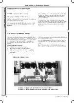
Page 31: ... remove the 2 19 INTERNAL WIRING EXTERNAL CONTROLS OpenTherm link To add wired external Room Thermostats Timers or Programmers proceed as follows 1 Isolate the mains supply to the boiler 2 Remove the front panel refer to Section 3 2 3 Swing the control box down into the servicing position refer to Section 3 3 4 Route incoming cables through the grommets in the bottom panel note grommets are blind ...

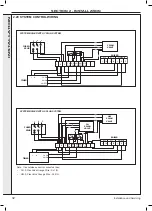
Page 32: ...N L N HW ON HW OFF Y PLAN VALVE SYSTEM BOILER WITH Y PLAN SYSTEM br br o g y b b g y g g L N E L N E CH ON R S ON HW ON HW OFF C S ON FUSED SPUR TIMER CH ON L N HW ON HW S PLAN VALVE CH S PLAN VALVE R S C S o BOILER L N MAINS IN SL 1 SL 2 E IN L IN L SYSTEM BOILER WITH S PLAN SYSTEM Note If an outside sensor is connected then CH S Plan Valve Orange Wire SL1 IN HW S Plan Valve Orange Wire SL2 IN IN...

Page 33: ...n If parts of the pipework run outside the house or if the boiler will be left off for more than a day or so then a frost thermostat should be wired into the system The frost thermostat should be sited in a cold place but where it can sense heat from the system Note If the boiler is installed in a garage it may be necessary to fit a pipe thermostat preferably on the return pipework EXAMPLE Connect...

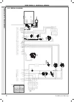
Page 34: ...S RX NC CHIP COM BUS GND CHIP COM BUS 5V CHIP COM BUS TX CHIP COM BUS RX CHIP COM BUS 24V CHIP COM BUS GND CHIP COM BUS 5V CHIP COM BUS RX MAINS LIVE MAINS NEUTRAL AUXILIARY LIVE IONISATION FLOW DHW DHW X7 2 WPS SIGNAL WPS GND FLUE FLUE RETURN RETURN 5 4 3 2 1 5 4 3 2 1 1 black grey red green blue brown green yellow orange pink violet yellow bk gy r g b br g y o p v y KEY 1 2 3 4 1 PE 1 2 N 2 3 L ...

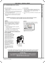
Page 35: ...ts refer to Gas Supply Section 1 8 Ensure that this inlet pressure can be obtained with all other gas appliances in the property working Gas Supply Gas Pressure Test Point ATTENTION IT IS A CONDITION OF THE MANUFACTURERS WARRANTY THAT THE BENCHMARK COMMISSIONING CHECKLIST IS FULLY COMPLETED AND LEFT WITH THE APPLIANCE A Electrical Installation 1 Checks to ensure electrical safety should be carried...

Page 36: ...nob E to the off position 7 Slacken the screw in the inlet pressure test point H and connect a gas pressure gauge via a flexible tube INITIAL IGNITION 1 Switch the electricity supply ON and check all internal and external controls are calling for heat 2 Move the On Off knob E into the on position Set the Boiler Temperature Control knob D to max The boiler will now go through its ignition sequence ...

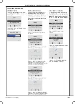
Page 37: ...stablished the following screen will be displayed MENU 60O C TO CYLINDER ON 60 C ON 60 C 15 C The temperature shown will be the actual Flow temperature At full output check the gas rate at the gas meter with no other appliances in use Refer to Table 2 for gas rates Ensure that with the boiler operating the dynamic gas pressure is able to obtain maximum output Refer to Table 1 Set the timer to be o...

Page 38: ...OFF Cylinder Demand On CH Demand On MENU 60O C TO CYLINDER ON 60 C ON 60 C 15 C Cylinder Demand Off CH Demand On MENU ON 60 C 15 C READY TIMER OR CYLINDER THERMOSTAT OFF Boiler Frost Protection occurs if Flow Temperature less than 5 C MENU BOILER FROST PROTECTION ACTIVE SWITCH OFF TEMPERATURE 19O C Service Due shown after 12 months operation see page 39 to reset MENU READY TIMER OR ROOM THERMOSTAT...

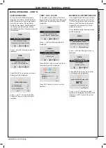
Page 39: ...Y NAME MAX OFF MAX OFF SELECT EXIT on the next screen to show the following EXIT SELECT MENU SERVICE COMPANY PHONE NUMBER CHANGE SERVICE INTERVAL FAULT HISTORY SERVICE COMPANY NAME Press SELECT and a screen similar to the folloiwng will be displayed SERVICE COMPANY PHONE NUMBER TEL NO 0 1 4 8 2 4 9 8 6 6 0 1 SET NEXT Press MENU SHOW EFFICIENCY LEVEL HOT WATER PREHEAT ON OFF SERVICE COMPANY PHONE N...

Page 40: ...T SELECT MENU VENT SYSTEM SENSOR READINGS FAULT HELP FAULT HISTORY Press SELECT and the following screen will be displayed EXIT SELECT FAULT HELP IGNITION LOCKOUT NO WATER FLOW LOW WATER PRESSURE Press MENU SHOW EFFICIENCY LEVEL HOT WATER PREHEAT ON OFF SERVICE COMPANY PHONE NUMBER SERVICE COMPANY NAME MAX OFF MAX OFF SELECT EXIT and MENU SHOW EFFICIENCY LEVEL HOT WATER PREHEAT ON OFF SERVICE COMP...

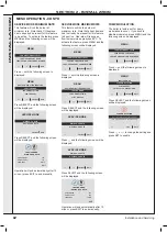
Page 41: ...HOW EFFICIENCY LEVEL HOT WATER PREHEAT ON OFF SERVICE COMPANY PHONE NUMBER SERVICE COMPANY NAME MAX OFF MAX OFF SELECT EXIT until the following screen is displayed EXIT SELECT MENU MAXIMUM FLOW TEMPERATURE SERVICE MODE SENSOR READINGS PUMP FAN VALVES Press SELECT and a screen similar to the following will be displayed EXIT PUMP FAN VALVES PUMP OFF DIVERTER VALVE POSITION FAN TARGET GAS VALVE CH 0 ...

Page 42: ...X OFF SELECT EXIT until the following screen is displayed EXIT SELECT MENU PUMP MODULATION PLOT GRAPHS SERVICE MODE MAXIMUM FLOW TEMPERATURE Press SELECT and the following screen will be displayed EXIT SELECT SERVICE MODE MAXIMUM CH RATE MINIMUM CH RATE Press MENU SHOW EFFICIENCY LEVEL HOT WATER PREHEAT ON OFF SERVICE COMPANY PHONE NUMBER SERVICE COMPANY NAME MAX OFF MAX OFF SELECT EXIT and the fo...

Page 43: ...the desired setting is displayed Press SET followed by EXIT to return to normal operation PLOT GRAPHS To plot graphs of Water Pressure Switch Live DHW Flow Rate DHW Temperature Flow Return Temperature Flame Status Outside Temperature or DHW Switched Live press MENU and the following screen will be displayed EXIT SELECT MENU SERVICE COMPANY NAME SERVICE COMPANY PHONE NUMBER SHOW EFFICIENCY LEVEL Pr...

Page 44: ...ulted 9 Explain boiler restart procedure 10 After installation and commissioning please complete the Commissioning Checklist before handover to the customer For IE its is necessary to complete a Declaration of Conformity to indicate compliance to I S 813 IMPORTANT 11 A comprehensive service should be carried out ANNUALLY Stress the importance of regular servicing by a Gas Safe Registered Engineer ...

Page 45: ...gas soundness check up to the gas control valve 6 When work is complete the front panel MUST be correctly refitted ensuring that a good seal is made Do NOT OPERATE the boiler if the front panel is not fitted 7 For cleaning of Ideal System Filter refer to section 3 32 8 If for any reason the condensate trap siphon has been removed ensure the trap is refilled with water before reassembling 9 Check t...

Page 46: ... into a lower position 3 To gain access to the mains wiring connections remove retaining screw press the retaining lug to the left and lift off the cover Position 1 2 Position 2 Clip REMOVAL 1 Loosen the 2 screws retaining the front panel at the underside of the boiler 2 Release catches at underside of the front panel by pulling downwards 3a Pull the underside of the front panel forward then lift ...

Page 47: ...s 9 To remove the fan first remove the venturi as above and release the 3 screws securing the fan to the burner Note a mounting spacer is fitted to the fan outlet on 32 model only 10 Remove the fan from the burner assembly When replacing check the sealing gasket is undamaged or replace as necessary and secure with the 3 screws 2 3 3 4 7 Noise Damper Fitted on 32 models only Mounting Spacer Fitted ...

Page 48: ... showing any signs of degradation Surface imperfections Cracks Discolouration Whitening Replacement of burner door sealing gasket 5b Remove the silicon seal from around the burner door location groove 6 Re new the seal and replace in reverse order 4 5 1 Refer to Sections 3 2 3 3 2 Remove the rubber condensate pipe from the top of the trap 3 Rotate the trap clockwise to disengage the trap and lift ...

Page 49: ...the heat exchanger connected 3 Refit the fan to the burner assembly Refer to Section 3 4 4 Refit the venturi to the fan and burner assembly Refer to Section 3 4 5 Refit the burner fan venturi assembly into the heat exchanger and secure Refer to Section 3 4 6 Refit the gas pipe and secure with the 2 clips Refer to Section 3 4 7 Reconnect the ignition detection earth fan leads 8 Swing the control pa...

Page 50: ...fit the venturi checking the sealing gasket is undamaged or replace as necessary and secure with the 2 screws Note a noise damper is fitted to the venturi inlet on the 32kW models Note a mounting spacer is fitted to the fan outlet on 32kW 11 Check the operation of the boiler Refer to Sections 2 24 2 27 When replacing ANY component 1 Isolate the electrical supply 2 Isolate water connections 3 Turn ...

Page 51: ...operation of the boiler Refer to Sections 2 24 2 27 8 3 14 RETURN THERMISTOR RENEWAL 1 Refer to Sections 3 2 to 3 3 2 Unclip the return thermistor 3 Disconnect the electrical lead from the thermistor 4 Reconnect the electrical lead to the new thermistor and reassemble in reverse order ensuring that the thermistor is securely fitted to the pipe on the thermistor locator tabs as shown 5 Check the op...

Page 52: ...into the burner door assembly and secure with the 2 screws ensuring correct orientation 7 Reconnect the ignition lead and earth 8 Check the operation of the boiler Refer to Sections 2 24 2 27 1 Refer to Sections 3 2 3 3 2 Disconnect the detection lead 3 Release the 2 securing screws and withdraw the probe 4 Ensure the sealing gasket is fitted to the replacement electrode and in good condition 5 Ca...

Page 53: ...23 5 Remove the 2 securing screws in the underside of the boiler casing and remove the valve 6 Remove brass injector from gas valve outlet and re fit into replacement valve 7 Replace in reverse order ensuring all seals are in good condition and the assembly is gas sound 8 Ensure all gas valve connections are gas tight with a gas soundness check up to the gas control valve 9 Check the operation of ...

Page 54: ...order 8 Turn power on and follow the on screen instrucitons as shown Installer Initialise PCB YES Press YES Installer Switch mains off wait 5s then switch mains on Installer Processing Select boiler model 1 14 Combi 26kW Natural Gas NEXT SELECT Press NEXT until the desired boiler output and gas type is displayed Then press SELECT Program this model 7 14 System 15kW Natural Gas BACK YES Press YES t...

Page 55: ...ontrols housing lid Refer to Section 3 20 4 Remove the electrical cover at the clips indicated Refer to Section 3 20 5 Disconnect the 2 electrical connectors carefully 6 Remove PCB from mounting posts by releasing the 4 clips 7 Replace the PCB and refit in reverse order 8 Check the operation of the boiler Refer to Sections 2 24 2 27 3 21 USER PCB REPLACEMENT 1 3 23 PRESSURE GAUGE RENEWAL 1 Refer t...

Page 56: ...he boiler Refer to Sections 2 24 2 27 3 25 PUMP AUTO AIR VENT REPLACEMENT 1 Refer to Sections 3 2 3 3 2 Close the isolating service valves and drain the CH boiler Refer to Section 3 22 3 Remove the burner Fan assembly if required for access Refer to Section 3 4 4 The auto air vent is retained in the pump body with a bayonet connection The air vent and float assembly is removed by turning the head ...

Page 57: ...he CH boiler Refer to Section 3 22 3 Remove the condensate trap Refer to Section 3 19 4 Remove the retaining clip to the rear of the housing 5 Pull out the sensor and disconnect the electrical connection 6 Refit in reverse order 7 Open the isolating valves and refill the CH system Refer to Section 2 15 8 Check the operation of the boiler Refer to Sections 2 24 2 27 3 28 FLOW THERMISTOR REPLACEMENT...

Page 58: ...fuse lead 8 Remove the horseshoe bracket and lift up the flue turret 9 Remove the securing screws and disconnect the flue outlet 10 Remove the 4 screws securing the heat exchanger fixing brackets 11 Remove the heat exchanger forwards lifting to clear the flow and return pipes 12 Refit in reverse order Ensure all wires and harnesses are in their correct position in order to prevent damage to them 1...

Page 59: ...rse order E Check the operation of the boiler Refer to Sections 2 24 2 27 Replacement 1 Refer to Sections 3 2 3 3 2 Close the isolating service valves and drain the CH boiler Refer to Section 3 22 3 Remove the clip securing the flexible connecting hose and disconnect 4 Remove the two securing screws from the top of the casing at the same time holding the ignitor bracket to prevent movement 5 Hold ...

Page 60: ...ves Remove magnet and vent 3 Remove drain valve cap open drain valve and vent 4 Open inlet valve slowly and flush out filter until water runs clear 5 Close the inlet valve Close the drain valve 6 Reinsert the magnet and replace the drain valve cap 7 Open inlet outlet valves refill system and vent 8 Restart the boiler WARNING Ensure that the magent pocket is kept dry Note Remember to re pressurise ...

Page 61: ...ection 4 13 No Connection to Primary PCB 5 Restarts within 15 minutes Turn power off and on Go to Section 4 6 Flame On before Gas Valve On Go to Section 4 7 Flow Thermistor Fault Go to Section 4 8 Outside Sensor Fault Go to Section 4 9 Return Thermistor Fault Go to Section 4 10 Fan Fault Replace PCB Go to Section 4 11 Low Water Pressure Less than 185V to boiler then check voltage at boiler mains i...

Page 62: ... and position refer to Section 3 17 Are these functioning correctly Check ignition electrode and associated harness for continuity visual condition and position refer to Section 3 15 Are these functioning correctly Check siphon and condensate drain pipework for blockage and rectify if necessary Boiler now working OK Restart boiler No No No No No No No No No No Yes Yes Yes Yes Yes Yes Yes Yes Yes C...

Page 63: ...ssociated harness for continuity visual condition and position Check if the condensate pipe is blocked Check if the flue is blocked Replace as necessary Check gas supply and rectify fault Check wiring from gas valve to PCB and replace if necessary otherwise replace the main PCB Replace spark generator and harness as necessary Replace ignition electrode and associated harness as necessary Replace g...

Page 64: ... to the Flame Sense Electrode Is there continuity between the Electrode and earth Is there continuity in the wiring from the primary PCB to the Thermistor 8 way connector connections 3 and 4 black and pink Does the Outside Sensor wiring between the boiler terminal strip and the PCB have continuity and is it securely connected 5 way low voltage connector connections 4 and 5 grey and black wires Is ...

Page 65: ...nections 5 and 6 black and red Is there 240Vac at the blue and brown connections to the 3 way connection on the Fan Does the wiring from the Water Pressure Switch to the PCB have continuity and is it securely connected Replace primary PCB Replace Fan Replace Water Pressure Switch Yes Yes Yes No No Yes Yes No Yes No No No Fit a new thermistor Rectify wiring connections Fill and vent the system and ...

Page 66: ...oes the fault disappear Are the Radiator Valves open Does the zone valve move to the appropriate position Is an Ideal Electronic Programmable Room Stat connected Is there 240Vac at A Is there a lin programmer insert aperture Replace main PCB No No Yes No Yes No Yes Yes Yes No Yes Yes Yes Ensure that the Timer and Room Thermostat are calling for heat Open the Radiator Valves Consult Electronic Prog...

Page 67: ...e from the main PCB to the user interface PCB have continuity and is it un damaged Is the Fuse on the main PCB OK Replace the user interface PCB still no display No No No No No No Yes Yes Yes Yes Yes Yes No Supply power to the boiler Connect the wiring from the terminal block to the main PCB securely Replace the wiring from the boiler terminal block to the Main PCB Connect the cable from the main ...

Page 68: ...ls of approved Ideal Parts Distributors are available on idealheating com Our Parts team are also available to help with your Ideal Spare Parts enquiries on 00353 0 1 961 7700 When calling and to ensure we can provide you with the most accurate parts information please ensure you have the following to hand Boiler Model Appliance GC Number Boiler Serial Number IMPORTANT NOTE Propane Boilers After i...

Page 69: ...69 SHORT LIST OF PARTS Installation and Servicing ...

Page 70: ...y their responsibility to register with the manufacturer within the allotted time period It is essential that the boiler is serviced in line with the manufacturers recommendations at least annually This must be carried out by a competent Gas Safe registered engineer The service details should be recorded on the Benchmark Service and Interim Boiler Work Record and left with the householder Failure ...

Page 71: ...ers complete DHW mode gas rate m3 hr or ft3 hr Central heating output left at factory settings Yes No If no what is the maximum central heating output selected kW Dynamic gas inlet pressure mbar Central heating flow temperature C Central heating return temperature C System correctly balanced rebalanced Yes COMBINATION BOILERS ONLY Is the installation in a hard water area above 200ppm Yes No Water ...

Page 72: ...l service in accordance with the manufacturers instructions and BS 7593 It is only acceptable to not have undertaken this if the service engineers attendance visit was in between annual services to attend a non water facing component SERVICE INTERIM WORK ON BOILER delete as appropriate Date Engineer name Company name Telephone No Gas Safe registration No Max rate CO ppm CO CO CO Min rate CO ppm CO...

Page 73: ...l service in accordance with the manufacturers instructions and BS 7593 It is only acceptable to not have undertaken this if the service engineers attendance visit was in between annual services to attend a non water facing component SERVICE INTERIM WORK ON BOILER delete as appropriate Date Engineer name Company name Telephone No Gas Safe registration No Max rate CO ppm CO CO CO Min rate CO ppm CO...

Page 74: ...FITTED BY PERSONS OTHER THAN THE BOILER INSTALLER visually check the integrity of the whole flue system to confirm that all components are correctly assembled fixed and supported Check that maximum flue lengths have not been exceeded and all guidance has been followed e g Gas Safe Register Technical Bulletin TB 008 where chimney flues are in voids The ECGA should be of the correct type as specifie...

Page 75: ...mbled fixed and supported as per instructions Check that flue and flue terminal are not obstructed Check that no seals e g Those on flue extensions have been displaced during installation Rectify if necessary Turn off appliance and call Ideal Technical Helpline for advice The appliance must not be commissioned until problems are identified and resolved If commissioning cannot be fully completed th...

Page 76: ...76 Installation and Servicing NOTES ...

Page 77: ...77 Installation and Servicing NOTES ...

Page 78: ...78 Installation and Servicing NOTES ...

Page 79: ...79 Installation and Servicing NOTES ...
Page 80: ...er an ISO 9001 registered quality management system FM 59915 At Ideal Heating we take our environmental impact seriously therefore when installing any Ideal Heating product please make sure to dispose of any previous appliance in an environmentally conscious manner Households can contact their local authority to find out how See https www gov uk managing your waste an overview for guidance on how ...

Reviews: