26
7.
ASSEMBLY OF THE DEVICE
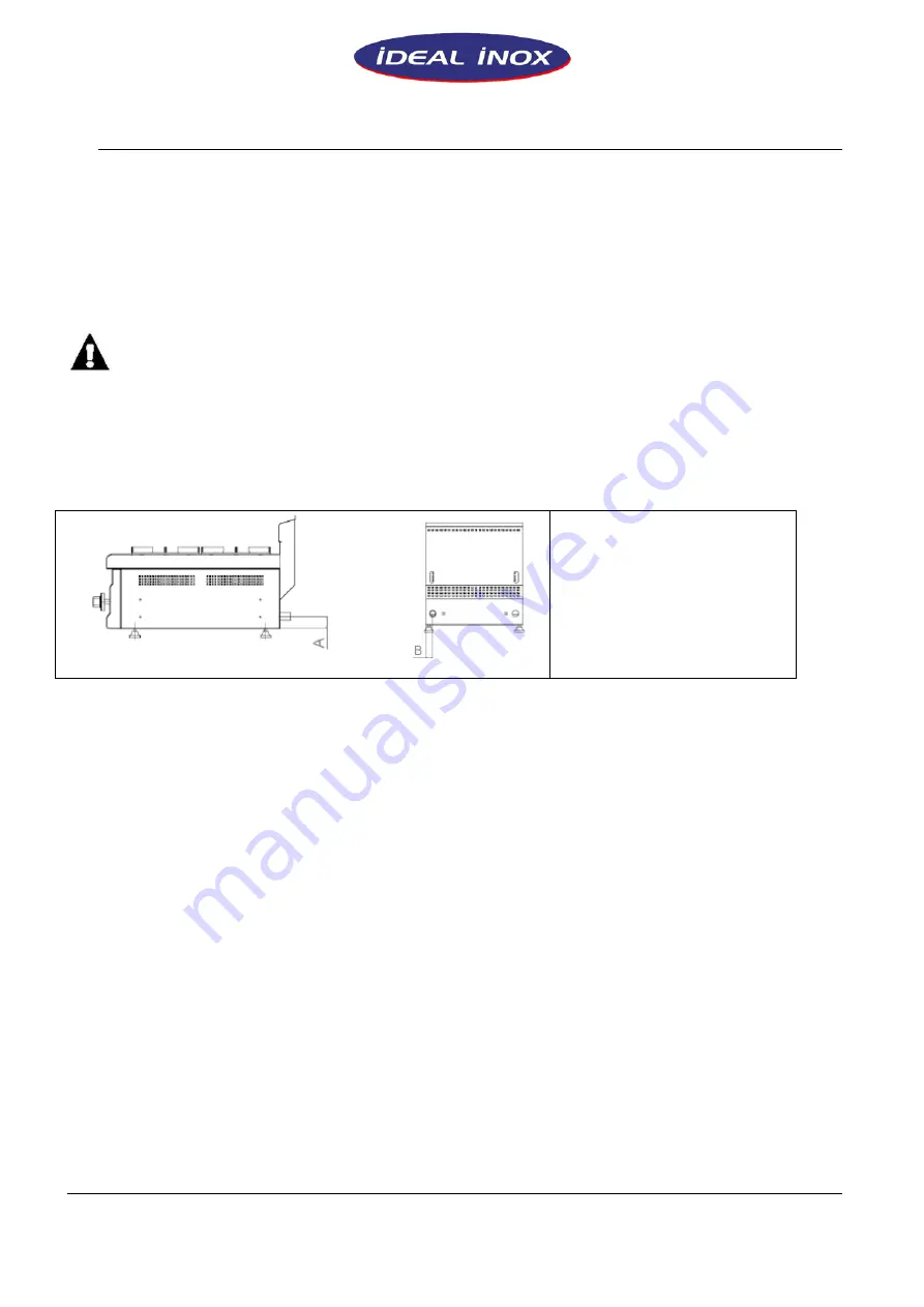
The inlet dimensions of the gas connection are defined in the
TECHNICAL SPECIFICATIONS schedule.
After the device is connected to the gas system, the gas leakage should
be checked by soap foam.
The air adjustment should be done if found necessary after the control
done by the personnel of the authorized service.
* The declared power of the device may never be changed as per the
user demands. All kinds of interventions to the valves and injectors for
such purposes will cease the guarantee coverage of the device.
Do not let use of spare parts in the device which are not original.
If the spare parts which are not obtained from our company are installed
on the device, the device will cease to be under guarantee coverage.
GAS CONNECTION DIMENSIONS
A: 30 MM
B: 50 MM
USED GAS:
G20 (NATURAL GAS)
LABEL SAMPLE
Summary of Contents for 1510-OCK
Page 6: ...6 4 DIMENSIUNI GENERALE I SEMNE DE AVERTIZARE SUPRAFA FIERBINTE ETICHET...
Page 12: ...12 8 PANOURI DE COMUTARE PANOU FRONTAL SERIA 700 A APRINZ TOR B VALVA DE SIGURAN...
Page 20: ...21 4 GENERAL DIMENSIONS AND WARNING SIGNS HOT SURFACE LABEL SAMPLE...
Page 26: ...27 8 CONTROL BOARDS FRONT PANNEL OF THE STOVES OF 700 SERIES A LIGHTER B SAFETY VALVE...
Page 31: ...32...
Page 36: ...37 4 DIMENSIONS GENERALES ET SIGNAUX D AVERTISSEMENT SURFACE CHAUDE D ETIQUETT...


