1
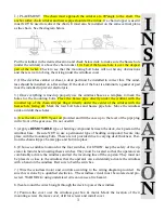
.) PLACEMENT: The chain must approach the wildcat at a 90ºangle to the shaft. The
anchor roller, chain wildcat and hawse pipe should all be in line. If a chain stopper is used it
must NOT be used to redirect the chain. It must also be installed on the same vertical plane
as the chain. See the diagram below.
Put the windlass in the desired location and check below deck to make sure the hawse hole
(under the wildcat) is above the chain locker. It is best if the hawse hole is over the deepest
part of the locker. Check to see that the mounting bolt holes will not hit any obstructions
and there is room to bring the wiring under the windlass cover.
2.) If the deck has camber or shear, a deck pad must be installed to correct this. The wind-
lass should be installed on a flat surface. If the deck of the boat is aluminum, a gasket or pad
must be installed to prevent electrolysis.
3.) Once everything is lined up properly use the windlass base as a template to mark the
holes for the mounting bolts. Place the hawse pipe directly under the wildcat with the
rounded top of the chain stripper finger directly under the center of the wildcat with the
hawse hole facing aft. Mark the four bolt holes and hawse pipe hole. Move the windlass
aside and drill these holes.
4.) Use the tube of 90 WT gear oil provided and fill the case up to the level of the pipe plug
in the front of the gear case. Do not overfill.
5.) Apply a
REMOVABLE
type of bedding compound between the deck, deck pad and the
windlass base. Be sure NOT to use a permanent type of bedding compound. Secure into
place with the mounting bolts. These are not provided due to varying deck thickness. Posi-
tion the chain stripper/hawse pipe and bolt into place.
6.) Choose a suitable location for the foot switches. CAUTION: keep the safety of the op-
erator in mind when locating these switches. They must be located so that the operator can
comfortably activate the windlass and tail the incoming line off the capstan. They must not
be placed so close to the windlass that the operator can accidentally activate the windlass
with a hand on the windlass. Bed sure to bed the switches.
7.)
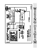
Wire the windlass motor and controls according to the wiring diagram provided. Be
sure this is done by a qualified electrician. The windlass circuit must be isolated and pro-
tected. WARNING: using undersized wire can cause a fire hazard.
8.) Seal around the wires brought through the deck to power the windlass.
9.) Position the cover over the windlass gear box & motor. Mark the location of the 4
mounting screws. Remove cover, drill for screws and install cover.
3


