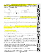
The chain wildcats
# 8
are driven by friction. The release wheel
#1
engages
and disengages the wildcats.
1.)
LOWERING THE ANCHOR ELECTRICALLY
– loosen the release
wheel
#1
on the side not being used and tighten the wheel on the side to be
used. It is necessary to secure the chain on the side not being used with a
chain stopper. Step on the down footswitch or engage the down button on the
remote control. Reverse this process to lower the 2nd anchor.
2.)
LOWERING THE ANCHOR – FREE FALL
– Caution must be used
when using the free fall feature. The operator must keep away from the outgo-
ing chain at all times. Disengage the clutch by turning the release wheel
#1
counter-clockwise. Release the chain stopper. The speed of the outgoing
chain can be controlled with the release wheel.
After the anchor is set
– set
the chain stopper. Do NOT allow the vessel to sit at anchor with the strain on
the anchor windlass. A chain stopper or suitable device must be used.
3.)
HOISTING THE ANCHOR
– Before hoisting the anchor check the
other wildcat to see if it is engaged or disengaged. See above. Engage the
wildcat by turning the release wheel
#1
clockwise. Push the up switch. If the
anchor is nestled in a hawse pipe, “inch” or “jog” the windlass the last few
feet.
Severe damage may result otherwise.
4.)
MANUAL OPERATION
- Insert the manual bar into the slot located in
the ratchet ring
#11
and pump back and forth.
5.)
HYDRAULIC SETTINGS
– The windlass is designed to run at 5.5
GPM at 1500 PSI.
5
CAPSTAN (line handling):
The capstan is directly keyed to the main shaft
and will always turn when the windlass is engaged. Wrap 3 or 4 turns around
the capstan going over the top of the capstan in a clock wise direction, and
keeping a small amount of tension on the line, step on the UP switch. If the
line slips apply more tension or add another wrap. The capstan may be used
independently of the wildcat by loosening the release wheel # 17 to disen-
gage the wildcat # 5.
CAUTION
: Do not wrap chain around the capstan.
WILDCAT (chain handling):
The chain wildcat #5 is driven by friction. The
release wheel #17 engages and disengages the wildcat. The chain may be
lowered electrically by using the down switch or by using the
FREE FALL
–
Caution must be used when using the free fall feature. The operator must
keep away from the outgoing chain at all times. Disengage the clutch by turn-
ing the release wheel #17 counter-clockwise. The speed of the outgoing chain
can be controlled with the release wheel.
After the anchor is set
– set the
chain stopper. Do NOT allow the vessel to sit at anchor with the strain on the
anchor windlass. A chain stopper must be used.
HOISTING THE ANCHOR with all chain
– Engage the wildcat by turning
the release wheel #17 clockwise. Push the up switch. If the anchor is nestled
in a hawse pipe, “inch” or “jog” the windlass the last few feet.
Severe damage
may result otherwise.
CIRCUIT BREAKER—
The windlass electrical system must be isolated and
protected. The breaker should be left OFF when the windlass is not in use.
This will prevent accidental activation. If the breaker trips from electrical
overload it can be reset immediately.
CAUTION
: Do not allow the windlass to operate without a load for any
long length of time as the motor is a series wound type that will heat up and
damage can result. It is not necessary to pause while pulling up the anchor as
the motor can run for several minutes at a time.


