SERVICING
Mini
Installation & Servicing
39
54 AIR PRESSURE SWITCH
REPLACEMENT
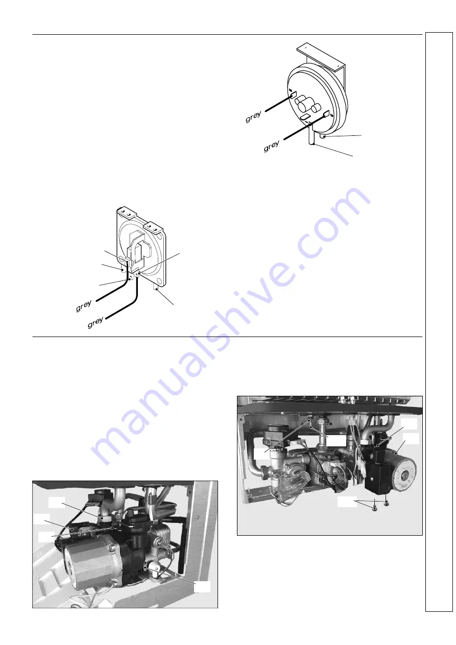
Two different types of air pressure switch may be used in the
boiler. Refer tho the following drawings in accordance with the
type of air pressure switch used.
1 Disconnect the electrical supply.
2 Remove outer and inner casing as explained in frame 36.
3 Disconnect the pressure sensing pipe from the air
pressure switch.
4 Disconnect the electrical harness from the air pressure
switch.
5 Undo the two screws which hold the air pressure switch to
the chassis and remove it.
6 Replace the switch.
7 Re---assemble in reverse order.
To correctly connect the venturi device to the air pressure
switch, refer to the illustration of frame 52 and to the
following illustrations in accordance with the type of
pressure switch used.
N.O.
N.C.
”L” connection
COM
”H” connection
(not used)
”L” connection
”H” connection
(not used)
55 PUMP REPLACEMENT COMPLETE
1 Disconnect the electrical supply.
2 Remove the front and right hand side casing panels (refer
to frame 36).
3 Release system pressure by opening the main circuit
drainage cock.
Do not release CH pressure using the pressure relief
valve. It may cause debris within the system to foul
the valve.
4 Disconnect the connector A.
5 Unscrew the locknut B and move the pipe upwards
freeing it from the outlet port of the pump.
6 Remove the fork C and the capillary pipe.
7 Remove the locking plate D right.
C
D
A
B
8 Loosen the connection E, remove the fork F and remove
the pipe G
9 Unscrew the two screws H that hold the pump on the
frame
10 Remove the pump towards the front of the boiler
E
I
G
F
H
Re---assemble in reverse order.
When reassembling the pump, check the correct location of
the O---ring gasket in the inlet port of the pump that seals the
connection between the pump and the brass group .
If the motor only needs replacing, disconnect the connector
A, unscrew the 4 screws I and remove the pump motor
forwards.
SER
VI
CI
N
G


