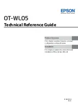
7. CABLE / CONTACT & HOUSING ASSEMBLY
Observing polarity of markings, push each contact into rear of housing until notched side snaps over spring, tug on cable to make sure
contact is locked into place.
DISASSEMBLING CONNECTORS (see illustration)
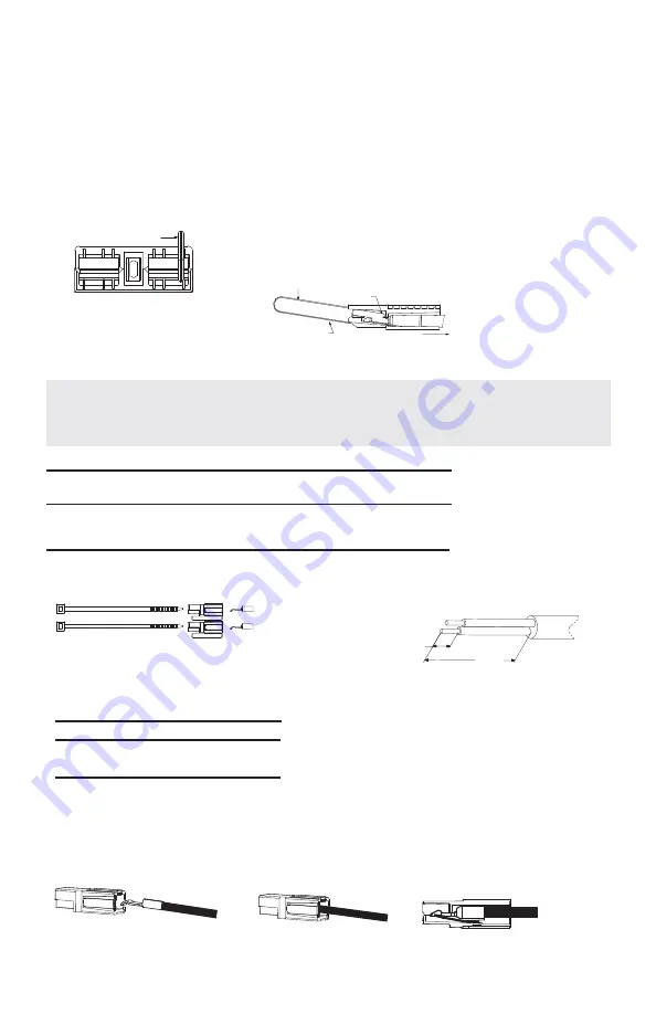
Switch off power fi rst. Remove contact by inserting extraction tool (cat. no. SBE160 / SBX175 - 969P1, SBE320 / SBX350 - 970P1) as
shown below (steps 1, 2, & 3).
CAUTION: Replace contacts individually on battery leads to reduce potential danger of shorting.
1. Insert extraction tool as shown between contact and housing to point A.
2. Press down to release contact from spring.
3. Pull cable to remove contact.
3. Pull cable to remove contact.
Contains two each of : housings, contacts, retaining pins & cable ties.
1. Single conductors use #12 to #18 AWG wire only. Strip to 0.31 inch (7.9 mm) off end of insulation.
2. Twin conductor cable #12 to #18. Strip back outer jacket 5.50 inches (139 mm). (See illustration). Then strip conductor insulation as in
(fi gure 1).
3a. To crimp: use the recommended tool. Crimping by other means may disturb contact position in housing and or produce high
resistance joints.
3b. To Solder: Not recommended.
Extraction Tool
2
3
Point A
Extraction Tool
Catalog
Wire Retaining
Number
Application
Contact
Size
Pin Length
6344
SBE80, SBE160, SBO60, SBX175
1331
#12/16
0.85
6305G1
SBE320, SBX350
1331
#12/16
1.00
6310G1
SBE320, SBX350
1332
#16/20
1.00
Crimp Tool
Catalog Number
Manual - cycle controlled
1309G2
Pneumatic - cycle controlled
1367G1
ASSEMBLY INSTRUCTIONS
NOTE: These assembly instructions apply only to the catalog numbers listed below
(SBE
®
, SBX
®
, SBO
®
).
[139]
5.5
[7.9]
0.31
Figure 1