


2. Crimp or Solder Contact to Cable Following Recommended Techniques
a.
Crimp power and ground contacts using 1309G4 hand tool or 1387G1 pneumatic tool (with appropriate die and locator, as noted in
Tables A and B), following all crimp tool instructions.
b.
Crimp auxiliary contacts using PM1000G1 hand tool, TM0001 Mil standard hand tool or TP0001 pneumatic tool (with appropriate
locator, as noted in Table C), following all crimp tool instructions.
c.
Soldering is recommended for cables with solid or minimal conductor stranding, ex. THHN type wire. Use rosin flux solder only.
Wrap cable strands. Melt solder into well, heat and insert stripped cable. Continue heating well until solder flows into wire, being
careful not to overflow onto contact surface. Do not solder-dip contacts. Cable clamps are required for solder connections (per
Underwriter’s Laboratories, Inc.), refer to Table E.
NOTES:
1. Follow all crimp tool instructions. Contact APP
®
Technical Support 978-422-3642 if instructions are missing or for further assistance.
2. SBS
®
75X: If using the cable clamp, secure the main clamp housing to the SBS
®
75X connector housing using the included screw and nut
before installing/inserting power and auxiliary contacts (Recommended torque is 8 inches - lbs). If using bundle wires, make sure bundle is
secured (not individual wires).
Table E: Cable Clamp Catalog Numbers
Connector Series
Clamp Number
Discrete Wire
Bundled
SBS
®
50
990
#8 - 6 AWG (10mm
2
)
-
990G1
#12 - 6 AWG (4 - 10mm
2
) -
5905
-
0.32 - 0.45 in (4.27 - 11.43mm)
SBS
®
75X
PSBS75XCLP1
#12 - 6 AWG (4 - 10mm
2
)
0.39 - 0.60 in (9.91 - 15.24mm)
PSBS75XCLP2
#12 - 6 AWG (4 - 10mm
2
)
0.35 - 0.55 in (8.89 - 13.97mm)
3. Insert Contacts into the SBS
®
Connector Housing
a. Main Power Contacts
1)
Observing proper polarity as marked on the housing, insert terminated contact in rear of housing with notched side of tongue next
to spring.
2)
Push terminated contact into housing until it snaps over end of spring; tug slightly to make sure contact is locked into place.
b. Ground Contacts (SBS
®
75G only)
1) Power/Ground contacts are marked with the ground symbol (
⏚
) and are used in the center location of the SBS
®
75G housing only.
2) Observing proper polarity as marked on the housing, insert terminated contact in rear of housing with notched side of tongue next
to spring.
3) Push terminated contact into housing until it snaps over end of spring; tug slightly to make sure contact is locked into place.
c. Optional Auxiliary Contacts (SBS
®
75x only)
1) Insert terminated contacts into the rear side of the connector housing using insertion tool
#11038G3
for #12 AWG and #16 - 14
AWG contacts and using insertion tool
#PM1002G1
for #20 - 16 AWG and #24 - 20 AWG contacts.
2) Use inspection tool
#PM1003GX
to ensure the auxiliary contact is properly seated in the connector housing.
3) To remove an auxiliary contact from the connector housing, use the extraction tool
#PM1003G1
from the front side of the
connector housing. Contact will release from the rear side of the connector housing.
NOTES:
1) With APP
®
logo facing up, the two UPPER holes are for PIN contacts, and the two LOWER holes are for SOCKET contacts.
2) Use the recommended auxiliary contact insertion, extraction and inspection tools, as noted in Table C.
3) Do not try to insert or extract the auxiliary contacts without the recommended insertion and extraction tools.
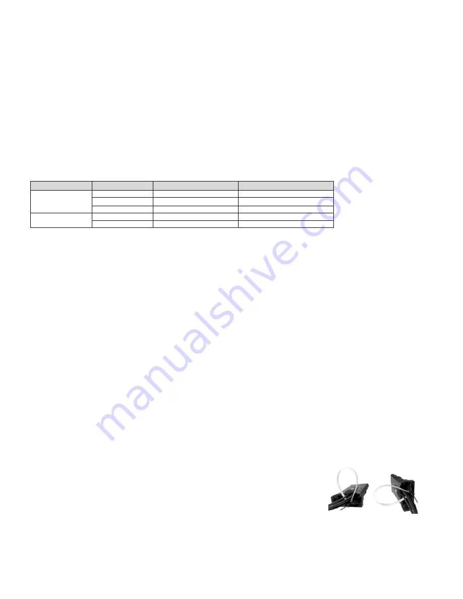
Using the Cable Clamp
1)
Secure the auxiliary wires using the included cable tie. Loop the tie through the two slots in
the clamp body so that the tie ratchet is outside the clamp body and tighten until fully snug.
2)
Screw the clamp to the main clamp body using the included self-tapping screws once the
power and auxiliary contacts are properly inserted. Screws should be torqued in an even
and opposite manner by alternating between screws through the tensioning process. The
bottom of the clamp should be equidistant on both sides from the clamp body when the
recommended torque value is achieved on both screws.
3)
Do not over tighten (Recommended torque is 5 in-lbs). If individual wires are being used,
visually inspect to make sure all wires are secured.


