18
Concord CX
- Installation
INST
ALLA
TION
INSTALLATION
19 COMMISSIONING AND TESTING
GENERAL
Check that all drain cocks are closed, that any stop valves
fitted to the flow and return pipes are open and that the
system has been filled and properly vented.
PURGING
Check that the electricity supply is switched OFF.
Remove the jacket lower front panel.
Extinguish all naked lights and open all doors and windows.
DO NOT SMOKE. Check that the gas supply is turned ON at
the meter and open the main gas inlet cock. Loosen the
union and allow air to be purged from the gas line until gas is
smelled. Refer to BS 6891 or IGE-UP-1 for further details.
Retighten the union.
TESTING FOR GAS SOUNDNESS
Close the gas supply cock at the meter.
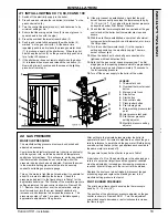
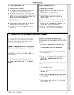
Remove the screw in the inlet pressure test point (Frames
20/21) and connect a gas pressure gauge to the test point.
Take particular care to ensure a gastight connection. Open
the gas supply cock at the meter and the appliance gas
cock; record the static pressure. Next, close the gas supply
cock at the meter. Wait for 1 minute for temperature
stabilisation then observe the pressure gauge over a period
of 2 minutes.
Any leaks must be cured.
Replace all pressure test point screws.
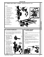
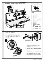
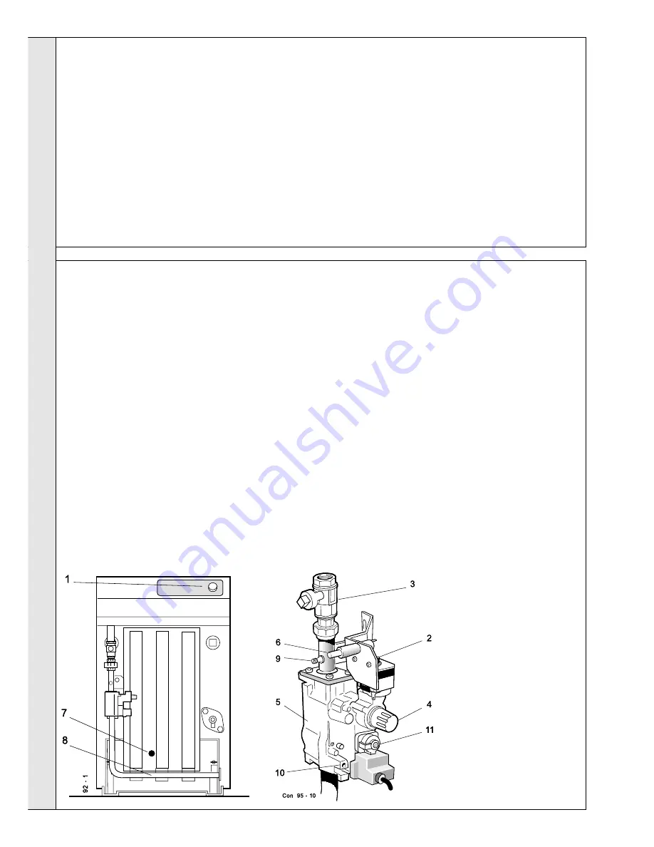
20 INITIAL LIGHTING CX 40, 50 AND 60
WARNING
.
If the pilot light or main burner flame is extinguished,
intentionally or otherwise, then no attempt should be made to
relight the gas until 3 minutes have elapsed.
1.
Switch off the electricity supply to the boiler.
2.
Twist the grey button on the gas valve clockwise then release
it.
3.
Turn the control thermostat knob (1) anti-clockwise to its
minimum setting at No.1.
4.
Ensure that the main gas inlet cock (3) is open (groove in
square head in line with the pipe).
5.
Press the overheat thermostat reset button (2).
6.
Push in and retain fully depressed the grey button (4), on the
gas control (5). At the same time repeatedly push in and
release the piezo generator knob (6) to produce a spark at
the pilot burner. When the pilot has lit keep the button (4) on
the gas valve fully pushed in for a further 20 seconds.
7.
If the pilot burner does not remain alight when the button (4)
is released, twist the grey button on the gas valve clockwise
then release it. Now wait at least 3 minutes and then repeat
the lighting procedure from step 5.
LEGEND
1.
Thermostat knob
2.
Overheat thermostat reset
button
3.
Main gas inlet cock
4.
Grey button
5.
Gas control valve
6.
Piezo igniter button
7.
Pilot viewing hole
8.
Burner setting pressure test
point
9.
Inlet pressure test point
10.
Pilot burner pressure setting
adjuster
11.
Manifold pressure setting
adjuster
8.
If the pilot cannot be established, check that the pilot burner
flame correctly envelops the thermocouple tip by 10-13 mm
(1/2"). If not, adjust the pilot burner pressure as described
under ‘Pilot Burner Pressure’.
9.
Check that the thermocouple lead connections at the gas
control and at the boiler limit thermostat are clean and secure.
10.
With the pilot flame established ensure that all external system
controls (time switch, room thermostat, etc.) are in the ON
position.
11.
Turn the control thermostat knob (1) to the required setting
and switch on the electricity supply. The main burner will now
light.
12.
When the boiler has lit check all gas connections for tightness
with leak detection fluid.
13.
Note that the gas control opens progressively. The first stage
gives a low opening pressure which is progressively increased
over a period of approximately 10 seconds to the full operating
pressure.
14.
Turn off the power supply to the boiler at the mains.
Summary of Contents for Concord CX40
Page 1: ......

