22
Concord CX
- Installation
28 SERVICING - continued
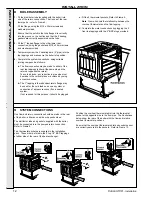
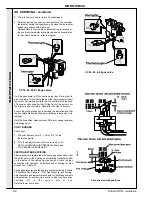
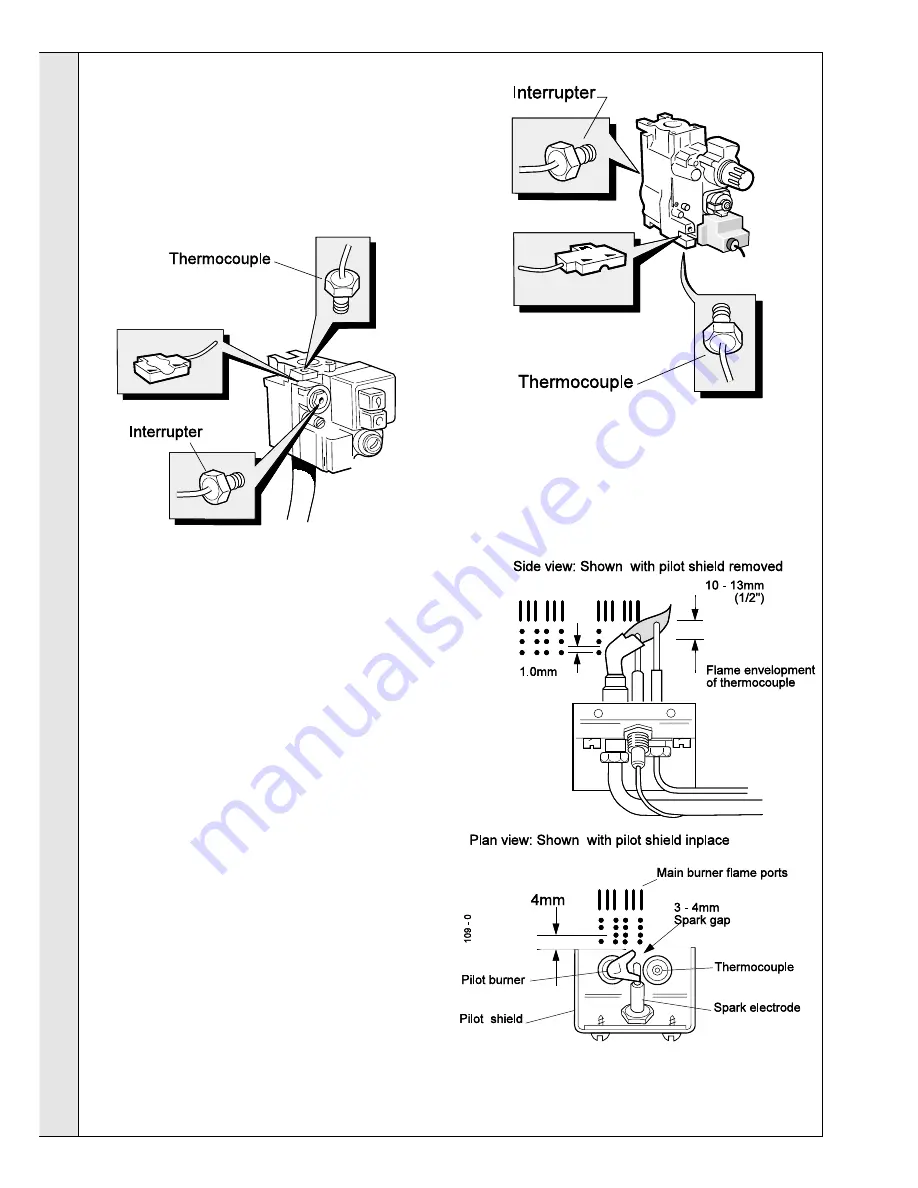
Pilot and electrode positions
6.
The pilot burner head is clean and undamaged.
7.
Carefully remove the push-on connections to the overheat
thermostat, noting their positions, and clean the thermostat
spade connections with steel wool.
Re-assemble in reverse order, remembering to reconnect
the overheat thermostat interrupter leads and connections
in the correct positions - refer to diagram.
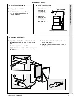
It will be necessary to fit the centre burner bar first in order to
give clearance for the pilot pipe and the thermocouple. Insert
the burner flat rear support fully into the central slot at the back
of the combustion chamber then lift the front of the burner over
the injector and pull forward. Repeat for the other 2 burners.
Ensure that care is taken not to damage the insulation and that
the front plate fits behind the burner retaining returns when it is
replaced.
Refit the flue baffles, cleanout cover, NOx duct, casing top panel
and casing door.
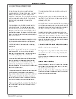
PILOT BURNER
Check that:
1.
The pilot flame covers 10 - 13 mm (1/2") of the
thermocouple tip.
2.
Turn the adjuster screw (refer to Frame 20 or 21)
ANTI-CLOCKWISE to INCREASE the flame and
CLOCKWISE to DECREASE it.
TESTING AFTER SERVICING
After re-assembly, restore the electricity and gas supplies. Light
the boiler (refer to the Lighting and Operating Instruction Label
on the inside of the casing front panel) and check the gas
connections for tightness, as detailed under ‘Testing for Gas
Soundness’ - Frame 19.
Check gas pressures and the gas rate; test as instructed in Frame
22 ‘Manifold Gas Pressure’, ‘Pilot Gas Pressure’ and Testing’.
Adjust any time and temperature controls to User’s requirements
and remember to reset any time control, which may have been
switched off, to the correct time of day.
Refit the lower front panel.
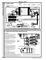
CX 70, 80, 90 & 100 gas valve
CX 40, 50, & 60 gas valve
SER
VICING
SERVICING
Summary of Contents for Concord CX40
Page 1: ......

