Concord CX -
Installation
23
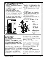
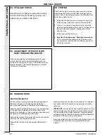
29 REPLACEMENT OF COMPONENTS - Refer to Frames 5, 24, 36 and 37.
GENERAL
WARNING.
Always
turn
OFF
the gas supply at the gas
inlet cock and switch
OFF
and
DISCONNECT
the
electricity supply
BEFORE WORKING
on the appliance.
1.
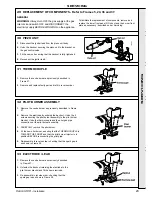
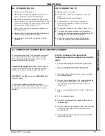
Remove the centre burner as previously described in Frame
27.
2.
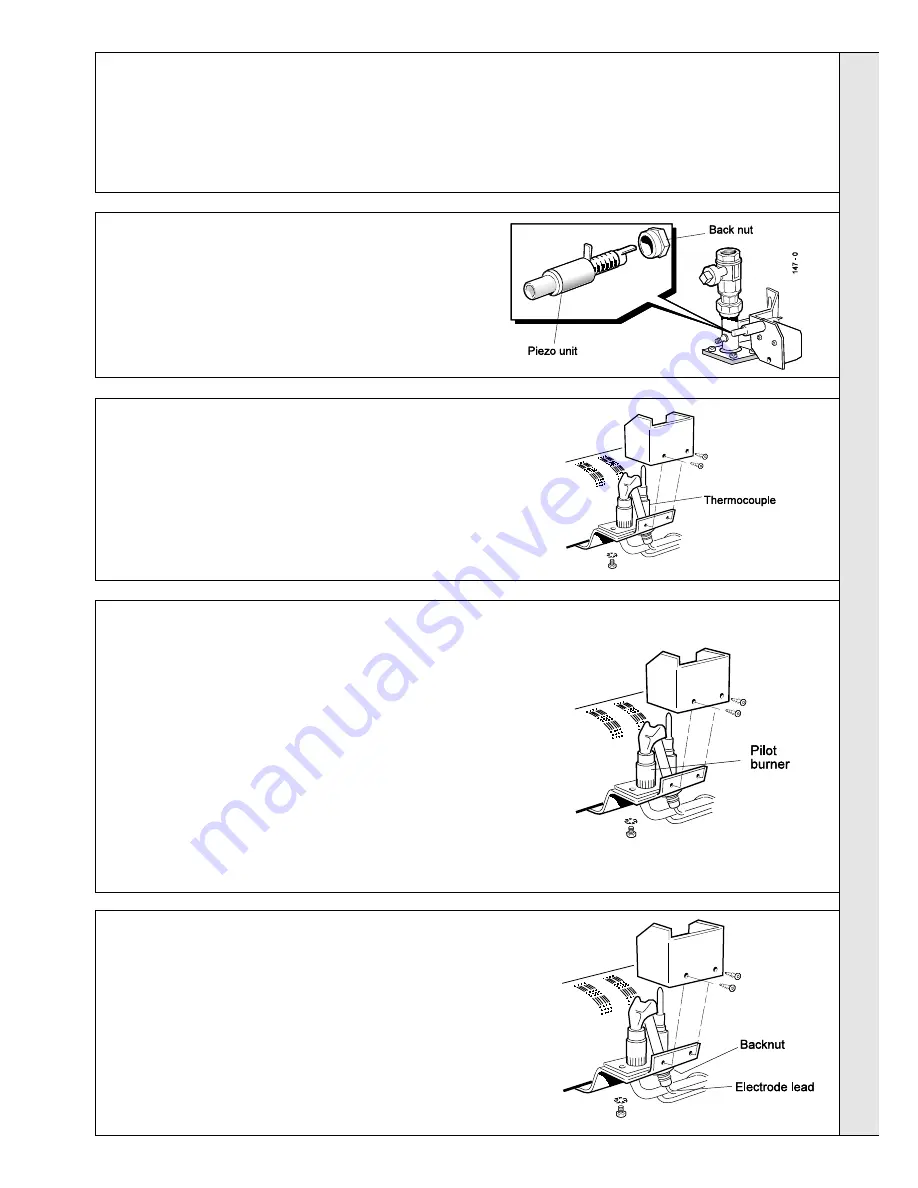
Remove the electrode by undoing the backnut. Undo the 2
screws securing the pilot burner assembly to the pilot burner
bracket. Undo the thermocouple and the pilot gas pipe
connections at the pilot burner assembly.
3.
CAREFULLY remove the pilot burner.
4.
Fit the new pilot burner, ensuring that the THERMOCOUPLE is
TOWARD THE FRONT and that the pilot burner injector is in
position BEFORE reconnecting the pilot pipe.
5.
Re-assemble in reverse order, checking that the spark gap is
as shown in Frame 28.
SER
VICING
SERVICING
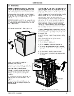
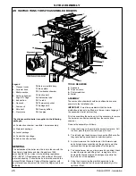
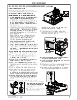
To facilitate the replacement of components, remove and
replace the lower front panel, NOx duct and the burner front
plate as necessary -described under ‘Servicing’.
1.
Disconnect the igniter lead from the piezo unit body.
2.
Undo the backnut securing the piezo unit to the bracket on
the gas control valve.
3.
Fit the new unit ensuring that the backnut is fully tightened.
4.
Reconnect the igniter lead.
1.
Remove the centre burner as previously described in
Frame 27.
2.
Remove and replace faulty part and refit in reverse order.
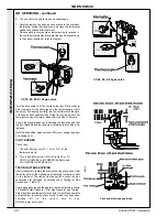
30 PIEZO UNIT
31 THERMOCOUPLE
32 PILOT BURNER ASSEMBLY
33 ELECTRODE / LEAD
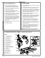
1.
Remove the centre burner as previously described
in Frame 27.
2.
Unfasten the backnut retaining the electrode to the
pilot burner bracket and fit the new electrode.
3.
Re-assemble in reverse order, checking that the
spark gap is as shown in Frame 28.
Summary of Contents for Concord CX40
Page 1: ......

