Concord CX -
Installation
25
SERVICING
SER
VICING
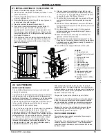
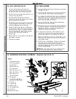
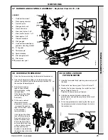
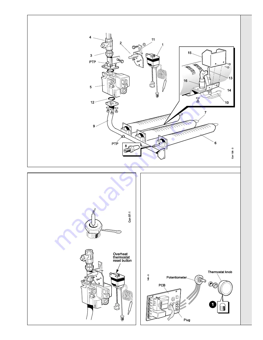
37 BURNER AND CONTROLS ASSEMBLY - Exploded View CX 70 - 100
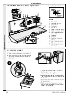
39 CONTROL SENSOR
POTENTIOMETER
1.
Undo the thermostat knob retaining screw and pull off
the knob.
2.
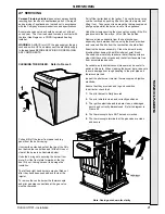
Remove the front lower panel. Refer to Frame 27.
3.
Slacken the 2 screws securing the control box front
panel. Refer to Frame 41.
Carefully lift it up and swing it forward.
4.
Undo the backnut and washer retaining the
potentiometer and pull the plug from printed circuit
board ‘No. 1C’.
5.
Fit the new potentiometer, ensuring that the lug on
the potentiometer body locates through the hole in
the controls box.
38 OVERHEAT THERMOSTAT
LEGEND
1.
Overheat thermostat
2.
Piezo spark generator
3.
Gas inlet union
4.
Main gas inlet cock
5.
Gas control valve
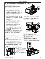
6.
Main (end) burner, 2 off
7.
Main (centre) burner, 1 off
8.
Main injector, 3 off
9.
Gas inlet manifold
10.
Pilot gas pipe
11.
Overheat thermostat/piezo
generator mounting bracket
12.
'O' ring seal
13.
Thermocouple
14.
Spark electrode
15.
Pilot draught shield
16.
Pilot burner
PTP
pressure test point
1.
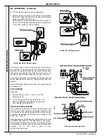
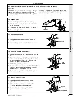
Undo the 2 screws retaining the thermostat/ bracket assy.
2.
Trace the thermostat capillary to the thermostat pocket,
remove the split pin from the thermostat pocket and lift out
the overheat thermostat phial.
3.
Remove the ‘push-on’
tags on the overheat
thermostat body, noting
their positions.
If the Option Kit is fitted
remove the tag from
Terminal 3.
4.
Fit the new overheat
thermostat / bracket
assembly in reverse order
; reconnect the push-on
tags to Terminals 1 and 2
on the overheat
thermostat body.
If the Option Kit is fitted
then refit the red wire to
Terminal 3 (refer to the
Option Kit instructions).
Ensure that the phial is
secured with the split pin
in the pocket on the rear
section and that the
capillary is rerouted along
the side casing in the clips
provided.
Summary of Contents for Concord CX40
Page 1: ......

