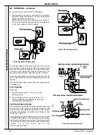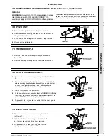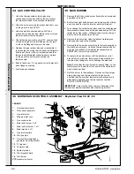
26
Concord CX
- Installation
SER
VICING
3.
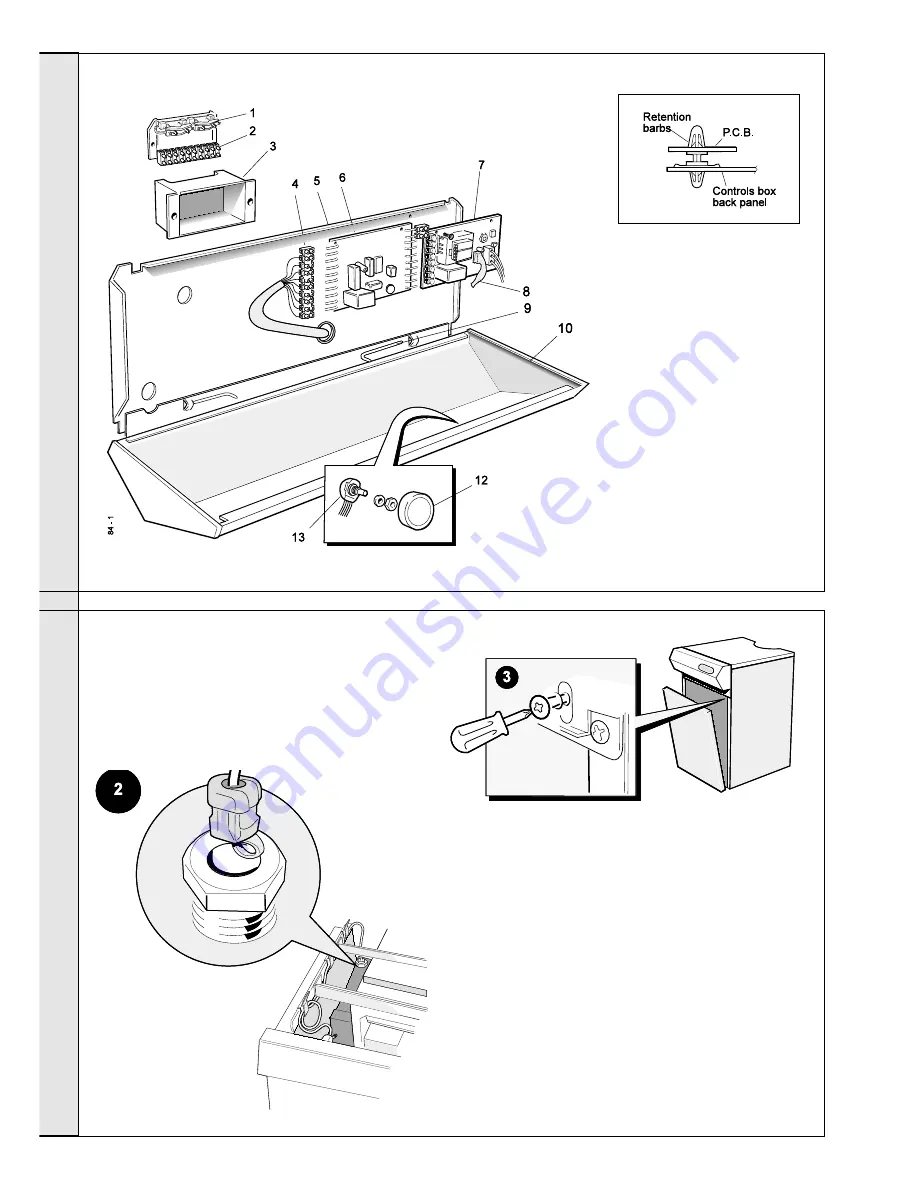
Slacken the 2 screws securing the control box
front panel.
Carefully lift it up and swing forward.
4.
Pull out the sensor plug from printed circuit board
‘No. 1C’ and remove the strain relief bush from the
back panel.
5.
Pull the sensor through the hole in the back panel
and the wire clips.
6.
Fit the new sensor and reassemble in reverse
order, ensuring that the lead is rerouted along the
casing in the clips provided.
Detail of Printed Circuit Board Support
SERVICING
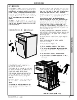
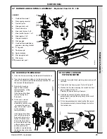
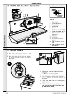
40 CONTROL BOX - Basic Boiler, Exploded View
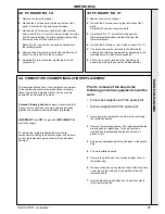
41 CONTROL SENSOR
1.
Remove the lower front panel. Refer to Frame 27.
2.
Remove the sensor from the thermostat pocket in
the rear heat exchanger section by removing the
Heyco bush.
LEGEND
1.
Wiring clamp.
2.
Connection box plug.
3.
Connection box.
4.
Terminal strip.
5.
Back panel.
6.
Printed circuit board 'No. 6A'.
7.
Printed circuit board 'No. 1C'.
8.
Water temperature control
sensor lead.
9.
Hinge pin.
10.
Controls box.
11.
Controls box fascia (not
shown).
12.
Water temperature control
knob.
13.
Water temperature control
potentiometer.
Summary of Contents for Concord CX40
Page 1: ......

