16
Concord CXC -
Installation
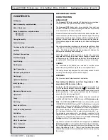
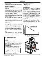
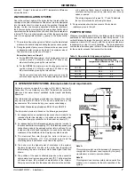
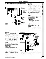
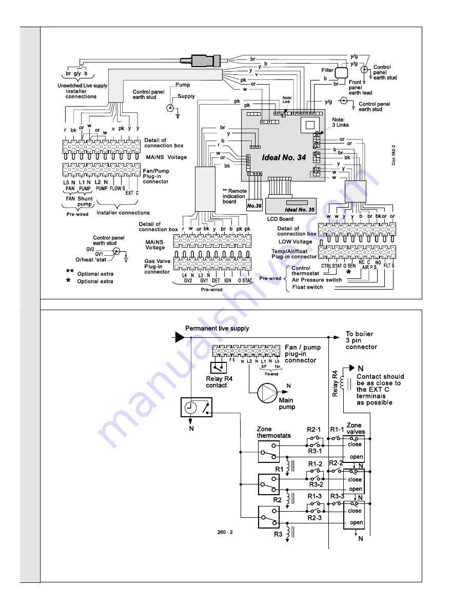
16 ZONES WITH BI-DIRECTIONAL MOTORISED VALVES
IMPORTANT
Terminal L2 may control the appropriate
pump(s) directly, provided that the total
running or starting current does not
exceed 6A (resistive or inductive): if this
rating would be exceeded, then
appropriate switchgear must be used to
control the pumps indirectly.
Three zones are illustrated but the
principles may be extended as required,
provided the above conditions are met.
Each relay will then require as many
contacts as there are zones.
Overrun
Since any zone may be the load during
overrun, all zones MUST individually be
able to satisfy the conditions in the
foregoing paragraph. If not all zones can
do this, then consider other means of
control detailed on other sheets.
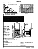
Normal operation
When any thermostat is satisfied while
others are calling for heat, power is
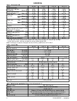
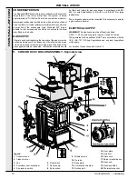
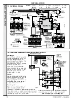
15 INTERNAL WIRING
At the start of the next call for heat (or the next clock period)
valves on the zones not calling for heat will motor-shut.
Water circulation system - refer to page 7
LEGEND
v
violet
pk pink
y/g yellow/green
or orange
y
yellow
w white
br brown
r
red
b
blue
bk black
INSTALLATION
INST
ALLA
TION
available via relay contacts to close the valve for that zone.
When all thermostats are satisfied (also when the clock period
ends) all relays will be off so the zone valves which were open
will remain open for the pump overrun period.
Summary of Contents for Concord CXC 116
Page 1: ......
Page 38: ...38 Concord CXC Installation NOTES ...

