24
Concord ESi
- Installation and Servicing
INSTALLATION
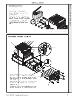
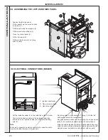
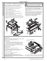
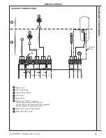
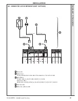
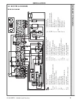
34 ELECTRICAL CONNECTIONS (BOILER)
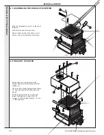
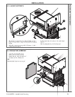
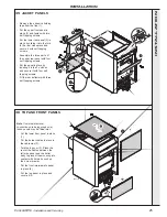
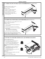
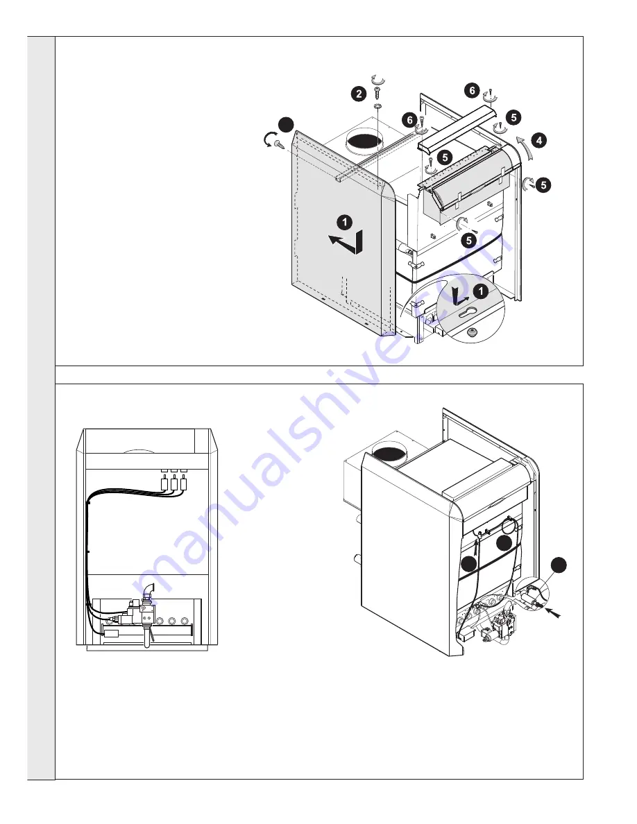
33 ASSEMBLING THE LEFT-HAND SIDE PANEL
-
Position the left side panel.
Fit the panel onto the pins and slide
to the rear (1).
-
Fit the panel to the front support (2).
-
Fit the panel to the stiffener (3).
-
Close the control panel (4).
-
Fit the 4 screwss (5)
-
Fit the protection cap (6), securing
with 2 screws.
-
Put the ionisation cable (5) in the cable ties to the RH side.
-
Connect the ionisation cable to the ionisation electrode
(electrode on the right-hand side) as well as the earthing
wire (6).
Note
Take care to separate as well as possible the ionisation cable
from the electrical harness of the gas train.
6
5
7
CON5282
-
Plug the ignition circuit connector (7) (plug 1) into the left
hand socket below the control panel.
-
Plug gas pressure switch connector (plug 2) and gas valves
(plug 3) into sockets as shown, below the control panel
-
Bring the cables together to form a neat bundle and secure
using the cable clamps, sliding the surplus between the left
side panel and insulation to avoid contact with hot parts
1.
Ignition transformer
2.
Gas pressure switch
3.
Gas valve circuit
2
1
3
CON5298
3
con9102
INST
ALLA
TION


