26
Concord ESi
- Installation and Servicing
INSTALLATION
con9058
37 ELECTRICAL CONNECTIONS (EXTERNAL)
The electrical connections shall be made in compliance
with the instructions given in the electrical diagrams
supplied with the boiler and the guidelines provided in the
manual. The electrical connection must comply with the
standards in force.
Connection must be made in a way that allows complete
isolation of the electrical supply - such as a double pole
switch, having a 3mm (1/8") contact separation in both
poles, or a plug and socket serving only the boiler and
system controls. The means of isolation must be
accessible to the user after installation.
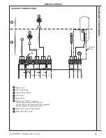
All the connections shall be made to the terminal block
provided for that purpose in the boiler control panel.
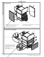
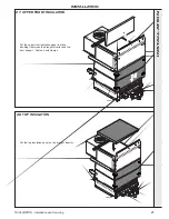
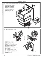
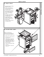
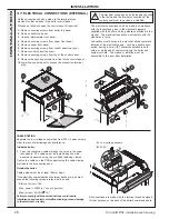
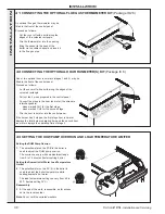
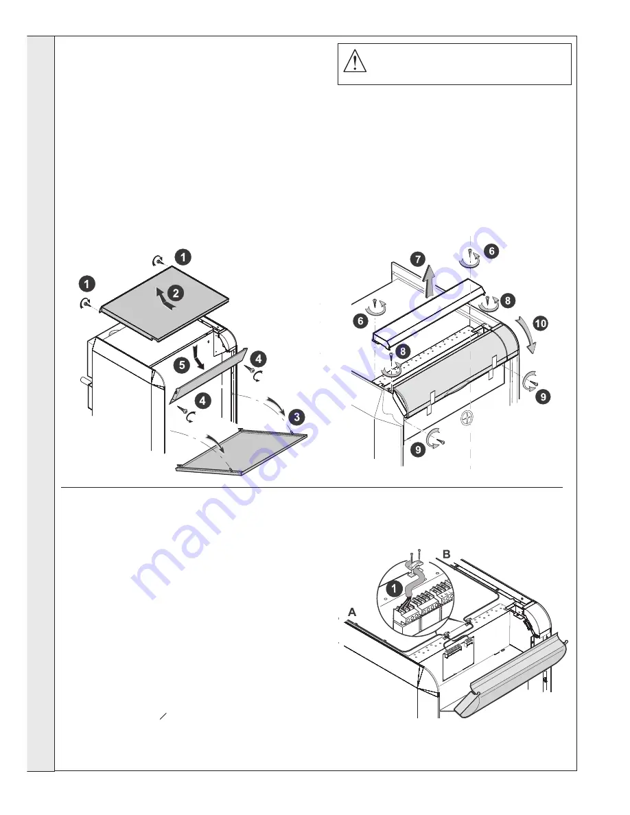
Proceed as follows to open the control panel (if required):
1.
Remove securing screws from boiler top panel.
2.
Remove boiler top panel.
3.
Unhook intermediate front panel.
4.
Remove securing screws from upper front panel.
5.
Remove upper front panel.
6.
Remove securing screws from control panel top cover.
7.
Remove control panel top cover.
8.
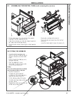
Remove securing screws from top of the control panel.
9.
Remove the securing screws from front of the control panel.
10.
Lower the control panel to access the connection terminal
strip.
con9056
con9057
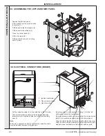
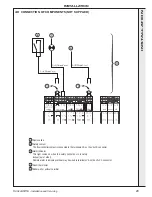
CABLE ROUTING
Separate the low voltage sensor wires from 230 V power wires in
order to prevent electromagnetic interference.
Inside the boiler:
1.
Feed the connection cables through the holes in the upper
rear panels. The cables must be routed along the side
panels and secured using the pre-fitted fastening clamps.
Tighten the cables on the PCB support using the cable clamps
provided in the accessories pack.
Outside the boiler:
Cable guides must be at least 100mm apart.
If the electrical characteristics of external devices (e.g. pumps)
exceed the following values a relay must be used.
- Start up current > 16A
- Max. power > 450W (or
1
/
2
cont. hp motor)
- Max. current > 2A COSO = 0.7
Failure to comply with these instructions could lead to
interference and control unit malfunctioning or even damage
to the electronic circuitry.
A.
Low voltage sensors
B.
230V
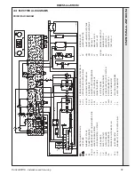
All connections are made with the terminal boxes designed
for that purpose on the back of the boiler's command board.
The electrical wiring has been thoroughly checked
in the factory and the internal connections of the
control panel must in no case be modified.
INST
ALLA
TION


