30
Concord ESi
- Installation and Servicing
INSTALLATION
CON9061
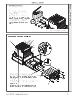
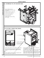
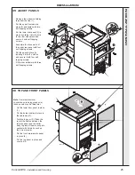
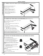
41 CONNECTING THE OPTIONAL FLUE GAS THERMOMETER KIT
(Package ID 28)
An optional flue gas thermometer may be
fitted to the front of the control panel.
Proceed as follows:
-
Cut the cover off with a knife along the
edges of the coloured rectangle.
-
Clip the thermometer into the opening.
-
Bring the sensor to the back of the
boiler via the cable channel and insert it
in the flue gas pipe.
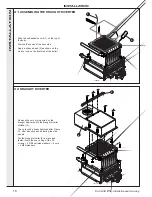
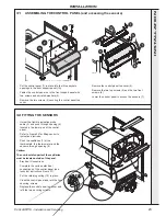
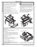
42 CONNECTING THE OPTIONAL HOUR RUN METER(S) KIT
(Package IC 8)
One or two optional hour run meters (stages 1 and 2) may be
fitted to the front of the control panel.
Proceed as follows:
-
Cut the cover off with a knife along the edges of the
coloured rectangle.
-
Pull out the 2 wires prepared in the control panel.
-
Connect the wires to the hour run meter (the wires are
interchangeable).
-
wires marked CH1 for the first stage.
-
wires marked CH2 for the second stage.
-
Clip the hour run meter into the control panel.
If the burner has 2 stages, the first stage hour run meter
displays the total burner operating time and the second hour
run meter displays the operating time of stage 2.
con9062
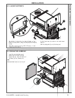
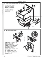
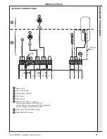
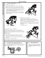
43 SETTING THE DHW PUMP OVERRUN AND LOAD TEMPERATURE LIMITER
con9063
1
2
Setting the DHW Pump Overrun
1.
The potentiometer on the PCB in the boiler is
used to adjust the DHW pump overrun.
The overrun can vary with an adjustment range
from 0 to 10 minutes (factory setting 4 min.)
Setting the Domestic Hot Water Load Temperature
Limiter
2.
The potentiometer on the P.C.B. in the boiler is
used to adjust the boiler temperature while
heating domestic hot water.
The load temperature setting can vary from 60 to
90
o
C (factory setting 75
o
C).
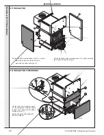
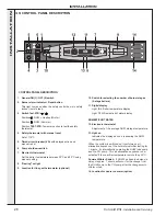
Reassembly
3.
At the end of the work, reassemble, as for access
but in the reverse order.
Note
.
Do not omit the serrated washers.
INST
ALLA
TION


