Concord ESi -
Installation and Servicing
33
INSTALLATION
49
COMMISSIONING AND TESTING
GENERAL
Check that all drain cocks are closed, that any stop valves fitted
to the flow and return pipes are open and that the system has
been filled and properly vented.
PURGING
Check that the electricity supply is switched OFF.
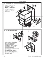
Remove the casing lower front panel.
Extinguish all naked lights and open all doors and windows.
DO NOT SMOKE. Check that the gas supply is turned ON at the
meter and open the main gas inlet cock. Loosen the union
and allow air to be purged from the gas line until gas is
smelled. Refer to BS 6891 or IGE-UP-1 for further details.
Re-tighten the union .
TESTING FOR GAS SOUNDNESS
Close the gas supply cock at the meter.
Connect a gas pressure gauge to the inlet test point. Take
particular care to ensure a gas-tight connection. Open the
gas supply cock at the meter and the appliance gas cock;
record the static pressure. Next, close the gas supply cock
at the meter. Wait for 1 minute for temperature stabilisation
then observe the pressure gauge over a period of 2
minutes.
Any leaks must be cured.
Replace all pressure test point screws.
Before turning the boiler on, make sure that the installation is
filled with water
.
Carry out the start-up operations in the order indicated below:
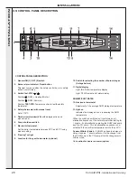
Refer to Frame 39 for identification.
•
Open the main gas shut-off valve.
•
Set the pump shutdown switch to .
•
Set the Summer / Winter switch
2
to the "Winter" position.
•
Switch on the electrical supply to the boiler.
•
Set all the controls (thermostats (7) and (12), external
controls etc.) so that heat is required.
•
Set the On / Off switch (1) to the "On" position.
•
The boiler will light and thermostat indicator light (8) will
illuminate. If it does not light the burner indicator (2) will be
illuminated. Press in and release the reset switch (2). The
controls will reset and attempt to light.
•
Check all connections for gas soundness, using leak
detection fluid.
50
INITIAL LIGHTING
48
FLUE CONNECTION
1.
Complete the flue connection.
2.
Details of flue outlet sizes are given in Table 2.
3.
Seal with an approved boiler putty.
INST
ALLA
TION

