4
Concord ESi
- Installation and Servicing
GENERAL
Safety Valve
A safety valve must be sized and fitted in accordance with BS.
6644 for every type of system. The valve should be set at 0.7
bar (10 lb/in.
2
) above the operating pressure in the boiler.
The maximum safety valve setting is 0.7 bar (10 lb/in.
2
) above
the maximum design operating pressure of 6 bar (87 lb/in.
2
).
Cold Feed/Open Vent
The independent cold feed and the open vent must comply
with BS. 6644 and be of the following minimum size.
1
WATER CONNECTIONS
GAS CONTROLS
Control is by automatic ignition of intermittent pilot; once the
presence of a flame has been proved the main gas valve opens
to give heat input according to thermostat settings. The mains
voltage supply is via a terminal strip connection at the control
box.
ELECTRICAL CONTROLS
The boiler is supplied with a control box providing full logic and
sequence control. A separate ignition transformer is fitted.
Details of the control panel are given in Frame 39.
FROST PROTECTION
If frost is likely, leave the boiler thermostat at a reduced
temperature setting and do not turn off the gas cock. Ensure
external controls allow the boiler to operate if necessary. Note
that this may not protect remote parts of the system, in which
case a separate frost thermostat should be fitted or the system
drained and the boiler shut down, as for Long Periods.
OPTION KITS
Hours run meter kit (IC8)
One or two hours run meters to measure 1st and 2nd stage
operation.
Flue gas thermometer kit (ID28)
Provides measurement of flue gas temperature.
DHW remote sensor kit (AD212)
DUTY
The range of boilers is suitable for: Combined indirect pumped
domestic hot water
and
central heating systems; Independent
indirect pumped domestic hot water
or
central heating systems.
Fully pumped systems may be open vented or sealed.
The range of boilers is NOT suitable for:
1.
Gravity DHW systems.
2.
Gravity heating systems.
3.
Direct domestic hot water supply.
WATER CIRCULATION SYSTEM
Due to the compact nature of the boiler the heat stored within the
castings at the point of shutdown of the burner must be
dissipated into the water circuit in order to avoid the overheat
thermostat tripping. The system controls must allow a pump
overrun period, after burner shutdown, of 3 minutes.
1.
The minimum flow rate given by:
min flow rate = 0.86.P m
3
/hour
45
where P = max. heat output of boiler (kW)
must be maintained whenever the boiler is firing and during
the pump overrun period.
2.
During the period of pump overrun there must be an open
circuit of adequate water volume and/or load.
3.
Pump selection should take account of the hydraulic
resistance given in the Data Tables on page 2.
PUMP POSITIONS
Whenever practically possible the circulating pump(s) should be
positioned so that it pressurises the system being served. The
vertical distance between the pump(s) and any cold feed and
expansion cistern MUST comply with the pump manufacturers
requirements in order to avoid cavitation. These requirements
override the information given in Frame 3 if the static head
required for the pump(s) exceeds that required for the boiler.
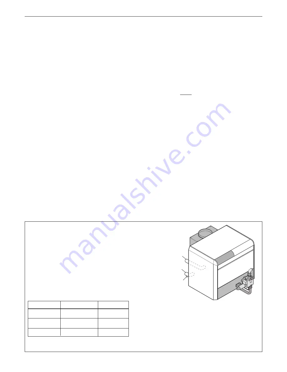
con9047
H
I
G
G
Drain (tapped 3/4")
H
2" threaded flow connection
I
2" threaded return connection
System connections H and I must be on the same side (either
on the right or on the left but never to opposite sides).
Note
The connections may be welded.
Boiler Size
Cold Feed
Open Vent
61 - 150
1"
1
1/4
"
151 - 300
1
1/4
"
1
1/2
"
301 - 600
1
1/2
"
2"


