Page 2
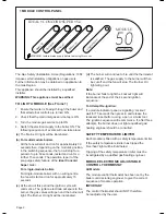
Mains on
Overheat
Lockout
Burner on
Lockout reset
IDEAL • CONCORD SUPER • S4
WARNING. Isolate mains supply before removing this cover.
50
MODULE
The Gas Safety (Installation & Use) Regulations: 1984
impose certain statutory obligations on gas users.
Further information may be obtained on application to
the Gas Region.
This appliance should be installed by a qualified
installer.
WARNING: This appliance must be earthed.
TO LIGHT A MODULE (See Frame 1)
1.
Ensure that water is flowing through the boiler and
that all external controls are turned ON.
2. Check that the main inlet gas service tap is ON.
3. Turn the module gas service tap to ON.
4. Switch the electrical supply to the boiler ON. The
following sequence of events will now take place:
(a)
The ‘Mains On’ light will be illuminated.
(b) For multi-module boilers
All the fans will start and run for approximately 30
seconds then, depending on the module’s position
in the switching sequence, the fan will stop for a
period of up to 50 seconds, restart and run for a
further 15 seconds. The operation is part of the
pre-purge safety feature of the
Ideal Concord
Super
boiler.
For single-module boilers
For single-module boilers with no wiring centre,
the fan will start and run for approximately 15
seconds.
(c)
At the end of this period the ignition cycle will
commence. The ignition electrode will spark to the
burner, the gas valves will open and the burner will
light. The ‘Burner On’ light will be illuminated.
(d)
The burner will continue to fire until the thermostat
is satisfied. The gas supply to the burner will then
be cut off and the fan will stop. The ‘Burner On’
light will go out.
Note:
If the burner fails to light the ‘Lockout’ light will
illuminate at the end of the 4 second ignition
sequence.
To Attempt Re-ignition:
If a module indicator panel is signalling ‘Lockout’
wait for 15 seconds then press in and release the
recessed reset button, using a pen or similar tool.
The ignition sequence will recommence. If, after three
attempts, the burner does not light a qualified gas/
heating engineer should be consulted.
SAFETY TEMPERATURE LIMITER
Each module is fitted with a safety temperature limiter.
If the safety temperature limiter has tripped the
‘Overheat’ light will be illuminated.
Tripping of the safety temperature limiter must be
investigated by a qualified gas/heating engineer.
MODULE ELECTRONIC ADJUSTABLE
CONTROL THERMOSTAT
All Models
The module control thermostat has been set by the
boiler commissioning engineer, to give the correct
sequence of module operation.
IMPORTANT
The control thermostat should NOT, therefore,
be readjusted by the user.
1 MODULE CONTROL PANEL


