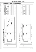
External
controls
via
OpenTherm
Master
and
Optional
Tank
Temperature
Sensor
Heating
Circuit
Pump
and
DHW
Tank
Charge
Pump
controlled
directly
from
MFR1
I1
I2
I3
I4
I5
I6
I8
I9
I10
1
2
3
1
2
3
4
1
2
1
2
1
2
3
4
5
6
1
2
3
4
1
2
1
2
3
1
2
3
4
5
6
1
2
3
4
5
6
7
8
L
N
PE
Tank
Temperature
Sensor
DHW
Tank
Charging
Pump
OpenTherm
Master
BMS
or
Room
Control
Pump
PELV
Interlock
Pump
control
0
‐
10V
OpenTherm
Header
DHW
Tank
/
Room
2
Room
1
Outside
Temp.
PELV
I0
I1
PWM
GND
10V
10V
GND
OT1+
OT1
‐
OT2+
OT2
‐
S1
GND
S2
GND
S3
GND
S4
GND
Fused
Spur
/
Isolator
Tank
Overheat
and
optional
Control
Thermostat
Mains
Supply
External
Controls
Heating
Circuit
Mains
Supply
Demand
inputs
230V
50Hz
Interlock
230V
50Hz
Auxiliary
MFR1
MFR2
MFR3
MFR4
C
N
O
PE
C
N
O
Mains
Voltage/230V
50Hz
Volts
Free
Contacts
L
N
PE
SL1
L
SL2
L
~
~
L
N
C
NO
PE
C
NO
External Controls via OpenTherm Master and Optional T
ank T
emperature Sensor
Heating Circuit Pump and DHW
T
ank Charge Pump controlled directly from MFR1
External
controls
via
Switched
Live/
or
OpenTherm/
or
Room
temperature
sensors
for
Two
Heating
Circuits
Heating
Circuit
Pumps
controlled
directly
from
MFR1
and
MFR2
I1
I2
I3
I4
I5
I6
I8
I9
I10
1
2
3
1
2
3
4
1
2
1
2
1
2
3
4
5
6
1
2
3
4
1
2
1
2
3
1
2
3
4
5
6
1
2
3
4
5
6
7
8
L
N
PE
Mains
Voltage/230V
50Hz
Volts
Free
Contacts
PELV
L
N
PE
SL1
L
SL2
L
~
~
L
N
C
NO
PE
C
NO
PE
C
NO
C
NO
GND
S4
I0
I1
PWM
GND
10V
10V
GND
OT1+
OT1
‐
GND
Mains
Supply
Demand
inputs
230V
50Hz
Interlock
230V
50Hz
Auxiliary
MFR1
MFR2
MFR3
MFR4
PELV
Interlock
Pump
control
0
‐
10V
OpenTherm
Header
DHW
Tank
/
Room
2
Room
1
Outside
Temp.
OT2+
OT2
‐
S1
GND
S2
GND
S3
Fused
Spur
/
Isolator
Room
Thermostat
HC1
OpenTherm
Master
HC
1
Heating
Circuit
2
Room
Temperature
Sensor
Mains
Supply
Heating
Circuit
1
Heating
Circuit
2
Pump
Pump
Room
Thermostat
HC2
Optional
HC
Room
Thermostats
Heating
Circuit
1
Room
Temperature
Sensor
OpenTherm
Master
HC
2
Optional
HC
Room
Controls
Optional
HC
Room
Temperature
Sensors
External Controls via Switched Live or OpenTherm or Room T
emperature Sensors for T
wo Heating Circuits
Heating Circuit Pumps controlled directly from MFR1 and MFR2
continued............
34
Installation & Servicing
SECTION 2 - INSTALLATION
INST
ALLA
TION
Summary of Contents for EVOMAX 2 30
Page 4: ...4 Installation Servicing...
Page 75: ...75 Installation Servicing NOTES...
Page 76: ...76 Installation Servicing NOTES...
Page 77: ...77 Installation Servicing NOTES...
Page 78: ...78 Installation Servicing NOTES...

