background image

42

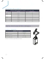
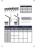
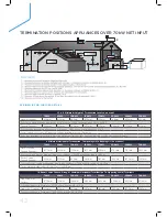
TERMINATION POSITIONS APPLIANCES OVER 70kW NET INPUT

SEE IGEM 10 FOR FURTHER DETAILS

1, 3 & 6  Minimum Height of Termination Located on a roof

70kW

80kW

100kW

120kW

150kW

200kW

240kW

300kW

Natural Draught

600mm

615mm

645mm

676mm

722mm

798mm

859mm

950mm

For other natural draught appliances use Distance = 1.5225 (net heat input kW) + 493.43

Fanned Draught

300mm

327mm

380mm

433mm

513mm

646mm

753mm

913mm

For other fan draught appliances use  Distance =  2.6644 (net heat input kW) +113.49 

For all sloped roofs over 20 degree pitch the terminal must be 1.5m away

If the flue termination is within 2.5m of an adjacent structure then these heights above the structure will apply

2 Minimum Horizontal Termination  To Openings Into Buildings (side or above)

70kW

80kW

100kW

120kW

150kW

200kW

240kW

300kW

Open Flue and 
Fanned Draught

1500mm

1600mm

1790mm

1975mm

2265mm

2740mm

3120mm

3690mm

For other open flue fan draught inputs use Distance = 9.5156 x (net heat input) + 833.91

Room Sealed  
Fanned Draught

600mm

675mm

820mm

960mm

1180mm

1540mm

1830mm

2265mm

For other room sealed fan draught inputs use  Distance = 7.232 x (net heat input) + 93.708

The minimum distance below in all cases is 2500mm

10 Room Sealed Fanned Draught  Minimum Horizontal Termination  To Opposing Walls/Terminals 

70kW

80kW

100kW

120kW

150kW

200kW

240kW

300kW

Opposing Flat  
Surface

1000mm

1231mm

1694mm

2156mm

2850mm

4006mm

4931mm

6319mm

For other inputs use Distance = 23.126 x (net heat input) – 618.84

Opposing Terminal

600mm

675mm

820mm

960mm

1180mm

1540mm

1830mm

2265mm

For other inputs use Distance = 19.32 x (net heat input) + 647.59

.

*4

*2

*2

*2

*9

*2

*5

*9

*1

*1

*1

*1

*1

*7

*7

*7

*9

*8

*8

*3

*3

*6

*10

.

*4

*2

*2

*2

*9

*2

*5

*9

*1

*1

*1

*1

*1

*7

*7

*7

*9

*8

*8

*3

*3

*6

*10

Summary of Contents for Evomax 30

Page 1: ...EVOMAX CONDENSING BOILER PRODUCT FLUE GUIDE WE HAVE IT COVERED...

Page 2: ...g industry Your phone or tablet can let you appreciate our Evomax range in a new dimension The Ideal Commercial Eye app uses the latest technology to project 3D renders from the page of this brochure...

Page 3: ...2 Introduction 4 13 Evomax 30 150kW 14 25 Evomax Cascade 30 600kW 26 37 Evomax Flue Options 38 39 Flue Types 40 46 Guide to Flue Installation Regulation 47 Condensate Pumps 48 49 Ideal Training Suppo...

Page 4: ...04 EVOMAX 30 150kW 5 year warranty subject to Terms and Conditions 5 years parts and labour warranty available subject to being commissioned by Ideal Boilers...

Page 5: ...05...

Page 6: ...1 turndown Compact one width height for easy siting Simple controls interface with large backlit display Comprehensive range of flue fixing and control options Designed for easy installation commissi...

Page 7: ...150 610 233 120 The following minimum clearances must be maintained for operation and servicing TOP DEPENDENT ON FLUE SIZE SIDES 25mm FRONT 450mm BOTTOM 300mm CLEARANCE BETWEEN MULTIPLE BOILER INSTAL...

Page 8: ...12 2 15 2 16 4 20 5 20 5 24 6 30 7 Gross kW 6 7 6 6 9 0 8 8 13 5 16 5 18 2 22 2 22 7 27 3 34 1 Gas Rate Max rate m hr 3 2 1 26 4 3 1 69 6 4 2 53 8 7 3 41 10 8 13 0 16 2 Flue Gas Flow Rate Max Rate m...

Page 9: ...ontent l 3 0 5 0 7 0 9 2 Dry Weight Kg 49 60 30 75 70 89 75 Optional kit available on 60 80 models for 100 150mm flue For use with vertical flues only BOILER EVOMAX Remote indication run alarm Hours r...

Page 10: ...mixed output cascades The boiler must have a maximum operating pressure of 6 bar and be suitable for heating and indirect hot water systems DIMENSIONS The condensing boiler range must have a universal...

Page 11: ...that fitting must be subtracted from the maximum flue extensions allowed for that flue option Note Horizontal terminal resistance includes 1 x 90 elbow When installing Evomax boilers with concentric...

Page 12: ...EATING CIRCUITS PRIMARY HWS 1 HWS SENSOR FROM HEATING CIRCUITS P1 P2 P3 S2 TO DRAIN S3 TANK SECONDARY HWS 1 P5 LOW LOSS MIXING HEADER SYSTEM LAYOUT TYPICAL SYSTEM BOILER LAYOUT Low loss header may not...

Page 13: ...13...

Page 14: ...14...

Page 15: ...15 EVOMAX CASCADE 30 600kW...

Page 16: ...are available for use with in line kits if required BACK TO BACK KITS Kits include all the in line contents plus the required special frame kits for such compact installations Both types of kit are a...

Page 17: ...0 552 DN80 80 125 100kW 1945 1650 552 DN80 100 150 UIN209800 120 150kW 1945 1650 552 DN100 100 150 HEADER KITS RATING HEIGHT mm LENGTH mm DEPTH mm DN FLANGE SIZE CONCENTRIC FLUE UIN209803 30 80kW 1945...

Page 18: ...5 2750 552 DN100 100 150 UIN209804 120kW 1945 2750 552 DN100 100 150 HEADER KITS RATING HEIGHT mm LENGTH mm DEPTH mm DN FLANGE SIZE CONCENTRIC FLUE UIN209806 30 80kW 1945 3300 552 DN100 80 125 100kW 1...

Page 19: ...00 930x1096 209901 190 3 30 60 100 2030 x 573 209801 30 60 100 480x1096 209903 200 2 100 1480 x 573 209799 100 930x1096 209901 210 4 30 40 60 80 2580 x 552 209803 30 40 60 80 1480x950 209905 220 3 2 x...

Page 20: ...209806 40 80 4 x 100 2030x1096 209908 530 6 30 5 x 100 3680x573 209806 30 5 x 100 2030x1096 209908 540 4 2 x 120 2 x 150 2580x663 209802 2 x 120 2 x 150 1480x1276 209904 550 N A N A N A N A N A N A 5...

Page 21: ...e boiler the flow and return flexible connections which reduce installation time Delivered with header kit connection pipe assembly non return valves pipe work connector all isolation valves pressure...

Page 22: ...2 100 150 150kW 1550 1650 642 100 150 3 X EVOMAX 30 150 KW 1550 HEADER KITS HEIGHT mm LENGTH mm DEPTH mm DN FLANGE SIZE CONCENTRIC FLUE 30 80kW 1550 1100 642 DN65 80 125 100 120kW 1550 1100 642 100 15...

Page 23: ...2 DN65 1100 x 642 209395 1 x 120 1 x 60 210029 180 2 DN65 1100 x 666 209395 1 x 150 1 x 30 210029 190 2 DN65 1100 x 666 209395 1 x 150 1 x 40 210029 200 2 DN65 1100 x 642 209395 2 x 100 210029 200 2 D...

Page 24: ...x 30 210020 290 3 DN80 1650 x 666 252437 1 x 150 1 x 100 1 x 40 210020 300 3 DN80 1650 x 642 252437 3 x 100 210020 320 3 DN80 1650 x 642 252437 2 x 100 1 x 120 210020 320 3 DN80 1650 x 642 252437 2 x...

Page 25: ...OILER PUMP HEATING PUMP TO HEATING CIRCUITS PRIMARY HWS 1 SECONDARY HWS 1 HWS SENSOR FROM HEATING CIRCUITS P2 P3 P4 P5 S2 S1 TO DRAIN TANK BOILER PUMP P1 TO DRAIN S3 LOW LOSS MIXING HEADER Low loss he...

Page 26: ...26 EVOMAX FLUE OPTIONS...

Page 27: ...27...

Page 28: ...80 125 100 150 Wall flue kit No 213264 213266 EVOMAX 60 80 HORIZONTAL CONCENTRIC FLUES OF LONGER LENGTHS LARGER FLUE DIAMETER Model 60 60P 80 80P Max flue length m 30 35 Flue Size 100 150 Wall flue ki...

Page 29: ...ust be fitted to all installations At least 1 off extension tube MUST be used in the installation This may be suitably cut to length if required To comply with CE certification Evomax boilers must be...

Page 30: ...elbow B N A N A 158773 158774 4 45 elbow pair B N A N A 158775 158776 5 Flat Weather Collar B C 152611 152612 158780 158780 6 Pitched Weather Collar B C 152609 152610 158779 158779 7 1m Extension conc...

Page 31: ...elbows is shown in Table 2 FLUE RESISTANCES FLUE SYSTEMS TABLE 1 TABLE 2 MAX PERMISSIBLE EQUIVALENT FLUE LENGTH INC TERMINAL RESISTANCE METRES CONCENTRIC OPEN FLUE Flue Size 80 125 100 150 80 100 Mod...

Page 32: ...2 100 100 150 220 120 100 150 365 150 100 150 430 Therefore this installation is acceptable as only a 2m run FOR OWN BUILT OPEN FLUE USE THIS EXAMPLE 1 CONCENTRIC HORIZONTAL FLUE FOR EVOMAX 40 Resista...

Page 33: ...17 6 2 x 90 elbow 2 x 1 9 3 8 Total Flue Resistance 17 6 3 8 13 8 b 9 5 3 5 0 1 2 6 0 2 b 7 5 3 5 0 1 2 6 0 2 EXAMPLE 2 CONCENTRIC VERTICAL FLUE FOR EVOMAX 80 Resistance m Flue Size 80 125 Max permiss...

Page 34: ...100 120 150 6 600kW 2 Combinations that include a 30 40 60 or 80 6 400kW 3 Propane Combinations of 30P 40P 60P 80P 6 400kW MULTILINE CASCADE The Multiline Flue Cascade is one of latest additions to t...

Page 35: ...erature Max Max Min Hmax Pmax 0 5 0 5 kW kW kW Pa C 30 7 5 400 40 9 7 9 0 72 40 10 60 15 80 20 100 25 600 80 120 30 150 37 5 30P 7 5 400 40 11 4 10 6 40P 10 60P 15 80P 20 At the maximum system capacit...

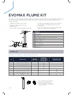
Page 36: ...an be used to relocate the flue terminal up to 10m Suitable for all Evomax up to 120kW Available for both 80 125 100 150 flue applications Plume kit offers terminal relocation up to 10m Includes stand...

Page 37: ...ME KIT 80 125 EVOMAX PLUME KIT 100 150 80 125 DIA FLUE MAXIMUM PERMISSIBLE FLUE LENGTHS M Evomax Model 30 30P 40 40P 60 60P 80 80P Y X 0 5 39 2 39 2 4 7 9 2 2 0 38 5 38 5 4 0 8 5 4 0 37 6 37 6 3 1 7 6...

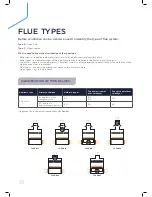
Page 38: ...n which a boiler s is installed which is not large enough to permit access for work other than maintenance via external access Plant room a room in a building that houses plant and machinery Open spac...

Page 39: ...ducts to outside atmosphere C11 C12 C13 C2 appliance flue connects to a common duct system for multi appliance installations the common duct system is part of the building C21 C22 C23 C 3 appliance w...

Page 40: ...industrial and commercial premises Building Regs Part J Combustion appliances and heat storage gives advice on how to comply with Building Regulations Clean Air Act A UK Parliament Act passed in resp...

Page 41: ...s CLEAN AIR ACT THE FACTS The Act applies to gas and other fuels fired appliance installations generally but with specific requirements for installations exceeding 333 kW net heat input including appr...

Page 42: ...above 70kW 80kW 100kW 120kW 150kW 200kW 240kW 300kW Open Flue and Fanned Draught 1500mm 1600mm 1790mm 1975mm 2265mm 2740mm 3120mm 3690mm For other open flue fan draught inputs use Distance 9 5156 x ne...

Page 43: ...B Enclosure Summer usage greater than 50 up to 75 Summer usage greater than 75 up to 100 High 2 5 1 2 Low 4 10 1 2 for boilers in use for more than 50 of the time during the summer months additonal v...

Page 44: ...ve to the outside atmosphere developing in the boiler room Interlocked to the gas appliance IMPORTANT The application of any other treatment to this product may render the guarantee of Ideal Boilers I...

Page 45: ...as an air vent However in addition the outlet should not be nearer than 150mm fanned draught to an opening into the building fabric formed for the purpose of accommodating a built in element such as a...

Page 46: ...al space it must itself be adequately ventilated as above The temperature within the boiler room shall not exceed 25 C within 100mm of the floor 32 C at mid height and 40 C within 100mm of the ceiling...

Page 47: ...8amps Alarm contact NC 4 Amps resistive Overheat protection 130 C Tank Capacity 2 0 Litres Maximum vertical head 4 5m Maximum horizontal length 30m IDEAL COMMERCIAL BOILERS CONDENSATE PUMP COMPATABILI...

Page 48: ......

Page 49: ...d by a dedicated national service team delivering help and advice to you and your customers throughout the year SALES Tel 0844 5436060 Fax 0844 5436181 TECHNICAL Tel 01482 498376 Fax 01482 498621 comm...

Page 50: ...50 NOTES...

Page 51: ...51 NOTES...

Page 52: ...vement in design and performance of its products and reserves the right to vary specification without notice Statutory rights of the consumer are not affected PLEASE NOTE The information in this broch...

Reviews: