18
xtra
-
Installation & Servicing
INSTALLATION
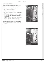
REAR VIEW
RETURN
FLOW
(Must be
connected
opposite side
to flow
connection)
(Must be
connected
opposite side
to return
connection)
im8482
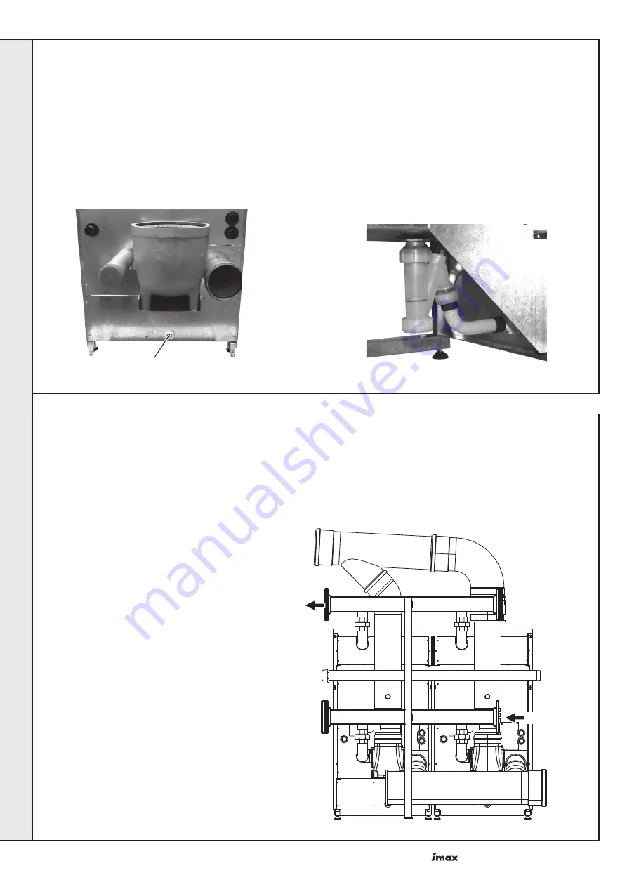
13 CONDENSATE DRAIN (Slave and Master)
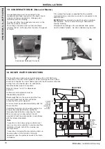
A condensate drain must be connected to the
condensate bulk head connector on the back of each
module and then connected to a drainage point,
preferably within the building.
The pipe size from the condensate connector on the
lower rear panel is 21.5mm.
The routing of the drain must be made to allow a
minimum fall of 1 in 20 away from the boiler, throughout
its length.
14 BOILER WATER CONNECTIONS
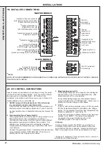
The boiler flow and return pipes are terminated with 2 x R2" BSP male
connections at the rear of the appliance. Water returning from the system
should be connected to a lower header pipe, with the flow water connection
coming from a top header pipe. An optional pre-
fabricated header pipe kit is available.
Refer to Frames 1 and 2 for dimensional
positions.
All flow and return pipework must be
independently supported.
Plastic plugs fitted on the open ends of the flow
and return pipes must be removed before
connecting the system pipework.
An air vent must be provided immediately after the
flow connection.
If installing the boiler onto an existing system it is
strongly recommended that the system be
thoroughly flushed before connecting the boiler.
When connecting to a new system it is still
important to flush the whole system in accordance
with the relevant standards.
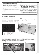
Condensate Bulkhead Connector
If the vertical flue header is specified the flue manifold
condensate drain connection must also be connected in the
same manner.
IMPORTANT.
Any external runs must be kept to a minimum
and insulated. This is to avoid freezing in cold weather
causing blocking.
All pipework and fittings in the condensate drain system
must be made of plastic. No other materials may be used.
Note.
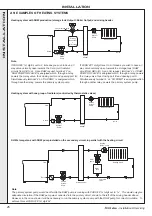
Connection to the boilers using manifolds must
use a reverse return principle to ensure equal flow
distribution through both of the modules, see
example below.
Connection of opposing flow and return points can
be made either on the LH side or RH side,
dependent upon the particular needs of the boiler
installation.
INST
ALLA
TION


