19
xtra
-
Installation & Servicing
INSTALLATION
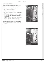
18 INSTALLING THE MAINS AND CONTROL WIRING (MASTER AND SLAVE MODULES)
1.
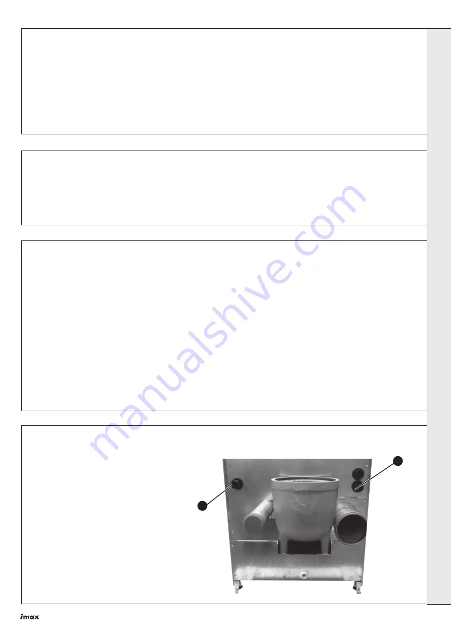
Route all 230V circuits in at the rear, through
conduit no. 1 on both Master and Slave
Modules.
2.
Route all low voltage remote sensor/control
cables for the master module through conduit
no. 2.
3.
Secure the cables with the cable clamps
provided on the main controls panel.
2
1
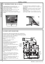
16 GAS CONNECTIONS
The boiler gas supply pipe is terminated in 2 x R1" BSP male
taper connections on the left-hand sides of the modules.
A gas header kit is available to combine the inlet connections
to a 2" manifold.
All gas supply pipework must be independently supported.
A minimum working gas pressure of 15mbar (6" w.g.) must
be available at the boiler inlet with the boiler firing.
Fit a gas supply pipe NOT LESS THAN 2" BSP to the boiler.
17 ELECTRICAL CONNECTIONS
Warning
. This appliance MUST be efficiently earthed.
A mains supply of 230V 50Hz is required to be fitted to both the
Master and Slave Modules (see terminals marked 'Mains In'
Frame 19). External controls should NOT be wired in series
with these mains inputs. Controlling the boiler in this way will
prevent the pump over-run sequence and may cause damage
to the modules. The supply wiring MUST be suitable for mains
voltage. Wiring should be 3 core PVC insulated cable NOT
LESS than 0.75mm
2
(24 x 0.2 mm) and to BS. 6500, Table 16.
The fuse rating should be 7A.
Wiring external to the boiler MUST be in accordance with the
current I.E.E. (BS7671) wiring Regulations and any local
regulations. For Ireland reference should be made to the
current ETCI rules for electrical installations.
Connection should be made in a way that allows complete
isolation of the electrical supply - such as a double pole
switch, having a 3mm (1/8") contact separation in both poles,
or a plug and unswitched socket serving only the boiler and
system controls. The means of isolation must be accessible
to the user after installation.
When making mains electrical connections to the modules it
is important that the wires are prepared in such a way that the
earth conductor is longer than the current carrying conductors,
such that if the cord anchorage should slip the current carrying
conductors become taut before the earthing conductor.
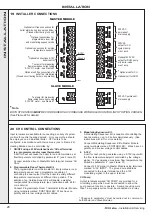
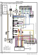
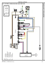
WARNING. Sensor cables must be separated from cables in
the 230V circuit. For this purpose three conduits are
provided. Refer to Frame 19 for terminal strip connections.
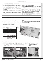
15 FROST PROTECTION
The boiler has built into its control system the facility to protect
the boiler only against freezing.
If the boiler flow temperature T
1
, falls below 7
o
C the pump will
be activated without the boiler firing.
If the flow temperature falls below 5
o
C the boiler will fire until
the flow temperature exceeds 10
o
C. The pump will stay
running for a further 5 minutes.
Central heating systems fitted wholly inside the building do
not normally require frost protection as the building acts as a
'storage heater' and can normally be left at least 24 hours
without frost damage. However, if parts of the pipework run
outside the building or if the boiler will be left off for more than
a day or so, then frost protection for the system is
recommended.
INST
ALLA
TION


